
Advanced settings and optimization
This chapter as a clean, readable HTML page.
The “Advanced settings and optimization” chapter of the Operating Manual, reproduced as a real HTML page. Anything unclear? Open the original PDF of just this chapter (pages 244-300) (also pinned top-left). Hub: all chapters.
Start using advanced settings only when you are confident with the system.
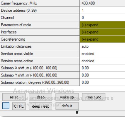 If you run into trouble, connect the beacon or modem to the PC via USB and use the DEFAULT button. It will upload “factory settings” to the board while keeping the device address untracked.
Radio Profiles Compatibility
In this section, we present different HW versions of different products:
Note: The suffixes “-3” and “-4” in product names (e.g., Super-Beacon-3, Super-Beacon-4, Modem HW v5.1-3) indicate the hardware version of the device. Hardware version 3 and hardware version 4 are the currently available variants. The hardware version is printed on the device label and shown in Dashboard. Different hardware versions may support different radio profiles – see the compatibility table below.
38 Kbps | 100 Kbps | 200 Kbps | 400 Kbps * | 500 Kbps | |
Modem HW v4.9 | Supported | Supported | Not Supported** | Not Supported** | Supported |
Modem HW v5.1 | Supported | Supported | Supported | Supported | Supported |
Modem HW v5.1-3 | Supported | Supported | Supported | Not Supported** | Not Supported** |
Super-Modem | Supported | Supported | Not Supported** | Supported | Supported |
Super-Modem-2 | Supported | Supported | Supported | Supported | Supported |
Super-Modem-3 | Supported | Supported | Supported | Not Supported** | Not Supported** |
Beacon Mini-RX | Supported | Supported | Not Supported** | Supported | Supported |
Beacon Mini-RX-2 | Supported | Supported | Supported | Supported | Supported |
Beacon Mini-RX-3 | Supported | Supported | Supported | Not Supported** | Not Supported** |
Super-Beacon | Supported | Supported | Not Supported** | Supported | Supported |
Super-Beacon-2 | Supported | Supported | Supported | Supported | Supported |
Super-Beacon-3 | Supported | Supported | Supported | Not Supported** | Not Supported** |
Super-Beacon-4 | Supported | Supported | Supported | Supported | Supported |
Industrial Super-Beacon | Supported | Supported | Not Supported** | Supported | Supported |
Industrial Super-Beacon-2 | Supported | Supported | Supported | Supported | Supported |
Industrial Super-Beacon-3 | Supported | Supported | Supported | Not Supported** | Not Supported** |
Industrial Super-Beacon-4 | Supported | Supported | Supported | Supported | Supported |
Industrial-RX | Supported | Supported | Not Supported** | Supported | Supported |
Industrial-RX-2 | Supported | Supported | Supported | Supported | Supported |
Industrial-RX-3 | Supported | Supported | Supported | Not Supported** | Not Supported** |
Industrial-RX-4 | Supported | Supported | Supported | Supported | Supported |
Industrial-RX-4 with Omni | Supported | Supported | Supported | Supported | Supported |
Beacon HW v4.9 | Supported | Supported | Not Supported** | Not Supported** | Supported |
Beacon Mini-TX | Supported | Supported | Not Supported** | Not Supported** | Supported |
Beacon Mini-TX-2 | Supported | Supported | Supported | Supported | Supported |
*400 kbps is used in Japan instead of 500 kbps
**Won’t be available because of specific radio chip configuration
Bold and Underlined is a default radio profile for a specific device
Examples of different configurations:
Starter Sets consist of different devices, so you check what types of devices you have, and it will depend on which radio profiles you can use
Example 1 – Modem HW v5.1 and Super-Beacon-2, 4
38 Kbps | 100 Kbps | 200 Kbps | 400 Kbps * | 500 Kbps | |
Modem HW v5.1 | Supported | Supported | Supported | Supported | Supported |
Super-Beacon-2 | Supported | Supported | Supported | Supported | Supported |
This table shows that in this configuration, you can use all profiles because both devices support them.
Example 2 – Modem HW v.5.1 and Super-Beacon-3
38 Kbps | 100 Kbps | 200 Kbps | 400 Kbps * | 500 Kbps | |
Modem HW v5.1 | Supported | Supported | Supported | Supported | Supported |
Super-Beacon-3 | Supported | Supported | Supported | Not Supported | Not Supported |
From this table, we can see that in this configuration, you can use 38 kbps and 100 kbps radio profiles because Super-Beacon-3 doesn’t support 400 kbps and 500 kbps (they won’t be available because of the specific processor configuration).
Example 3 – Modem HW v.5.1-3 and Beacon Mini-RX-3
38 Kbps | 100 Kbps | 200 Kbps | 400 Kbps * | 500 Kbps | |
Modem HW v5.1-3 | Supported | Supported | Supported | Not Supported | Not Supported |
Beacon Mini-RX-3 | Supported | Supported | Supported | Not Supported | Not Supported |
From this table, we can see that in this configuration, you can use 38 kbps and 100 kbps radio profiles because Modem HW v5.1-3 and Beacon Mini-RX-3 don’t support 400 kbps and 500 kbps (they won’t be available because of the specific processor configuration).
Example 4 – Modem HW v.5.1, Super-Beacon-2 and Beacon Mini-RX-3
38 Kbps | 100 Kbps | 200 Kbps | 400 Kbps * | 500 Kbps | |
Modem HW v5.1 | Supported | Supported | Supported | Supported | Supported |
Super-Beacon-2 | Supported | Supported | Supported | Supported | Supported |
Beacon Mini-RX-3 | Supported | Not Supported yet* | Supported | Not Supported | Not Supported |
From this table, we can see that, in this configuration, you can use 38 kbps and 100 kbps radio profiles because Beacon Mini-RX-3 doesn’t support 400 kbps or 500 kbps (they won’t be available due to the specific processor configuration).
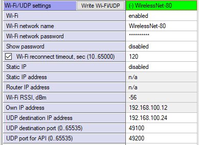
Wi-Fi Settings for Super-Modem
You can use Wi-Fi for coordinate streaming to another PC. In this chapter, we explain how to do that. For more information, see chapter 5.1.
Wi-Fi Settings Menu in Dashboard
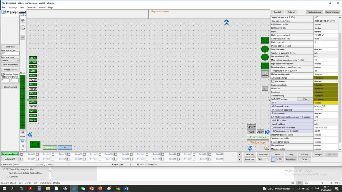 When Super-Modem is connected to the PC via USB, expand “Wi-Fi/UDP settings” in the settings bar.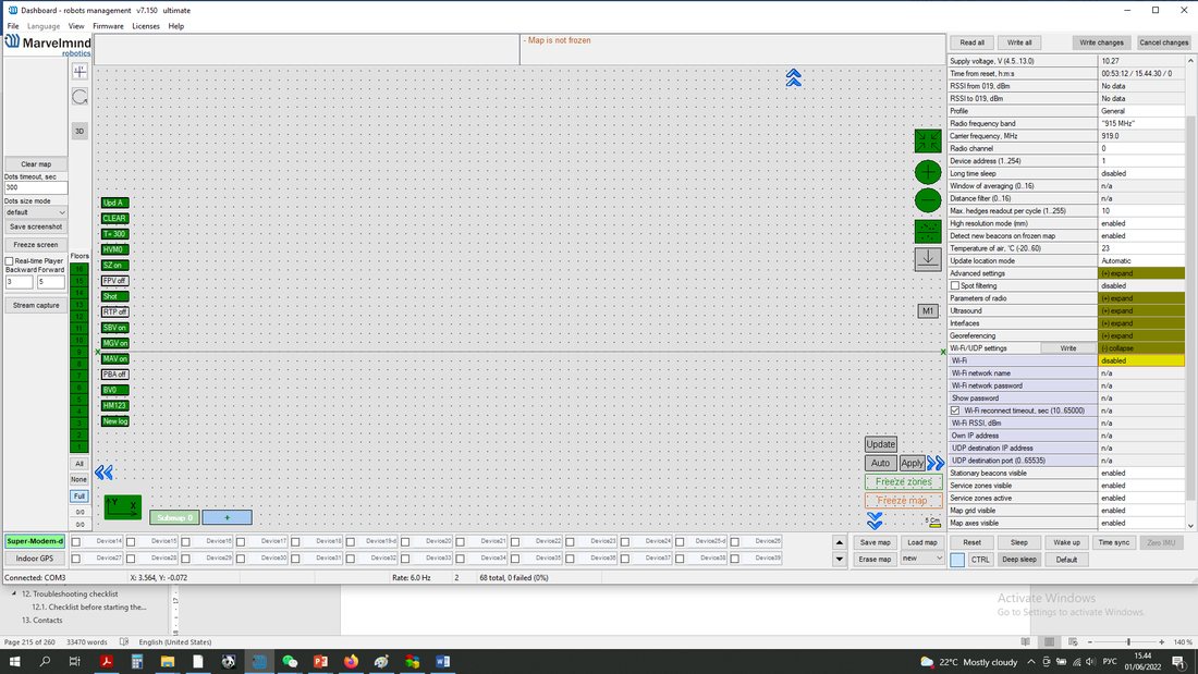
- Insert the Wi-Fi network name and Wi-Fi network password of your wireless connection and press the “Write” button
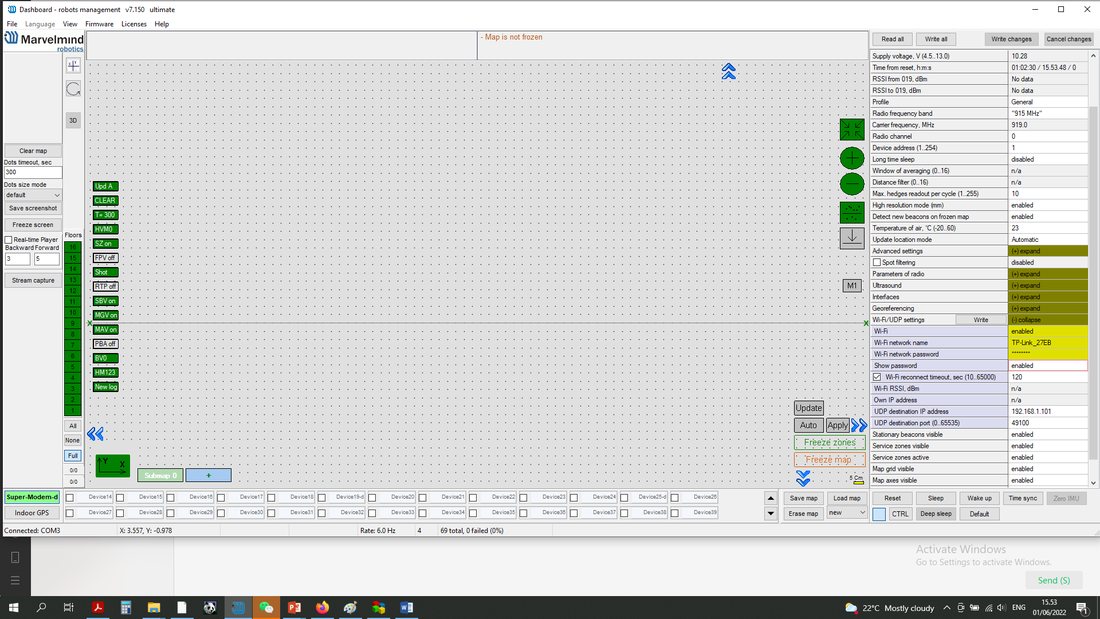
- After this, “Wi-Fi/UPD settings” bar turns to green and shows your network name.
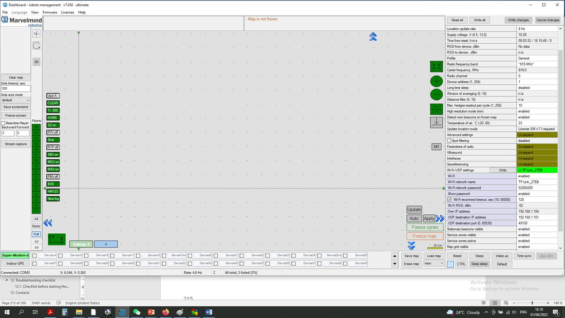
- Insert UDP destination IP address and UDP destination port of device to which you will stream coordinates and press write button.
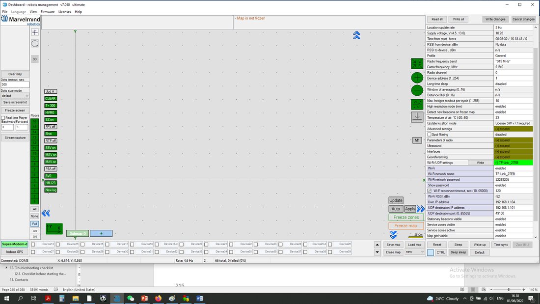
- Wi-Fi settings completed.
Static IP
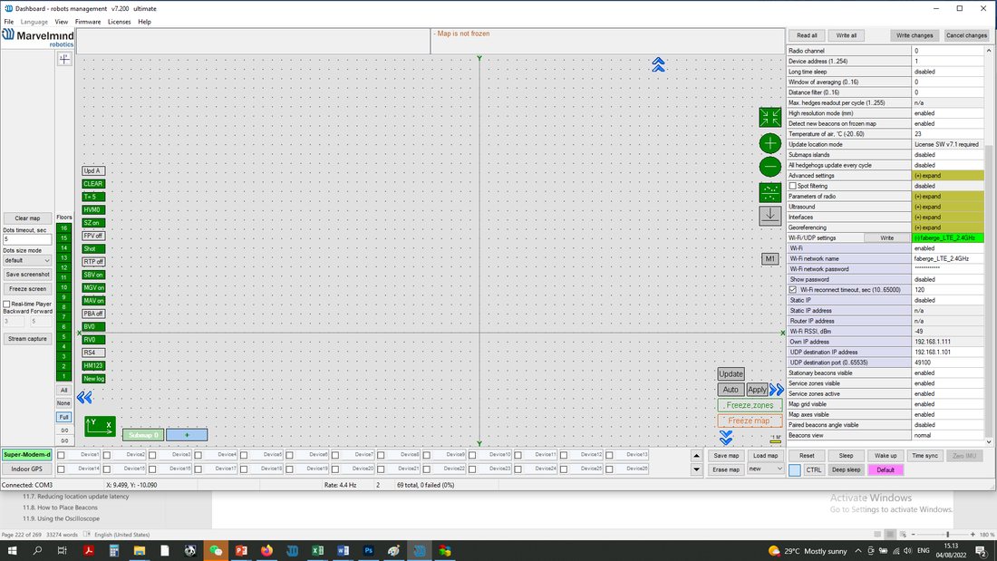
Enter the IP address in IPv4 format (An IPv4 address has the following format: x . x . x . x where x is called an octet and must be a decimal value between 0 and 255.) and the IP address of the router that is used for the Wi-Fi connection. Press the Write button:
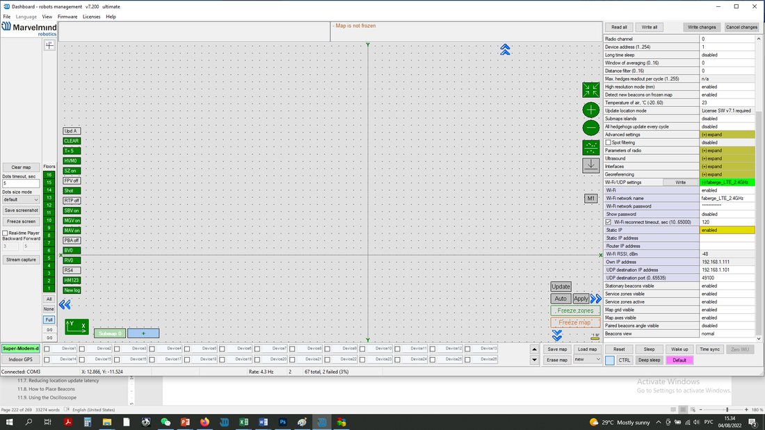
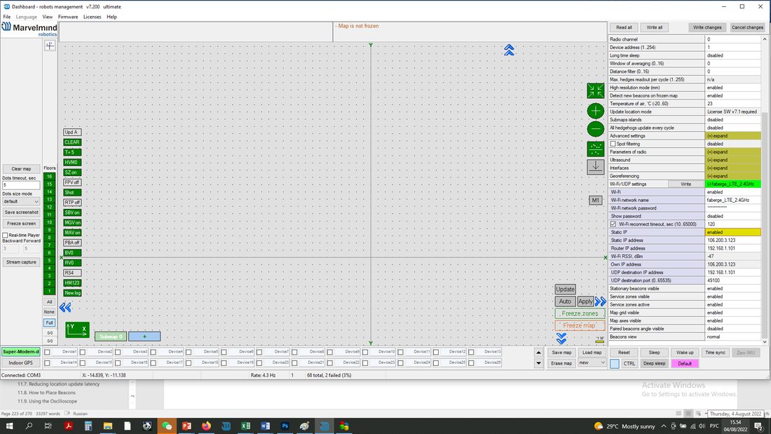
Static IP settings completed.
Time Division Multiple Access (TDMA) Sequence
Only applicable in IA.
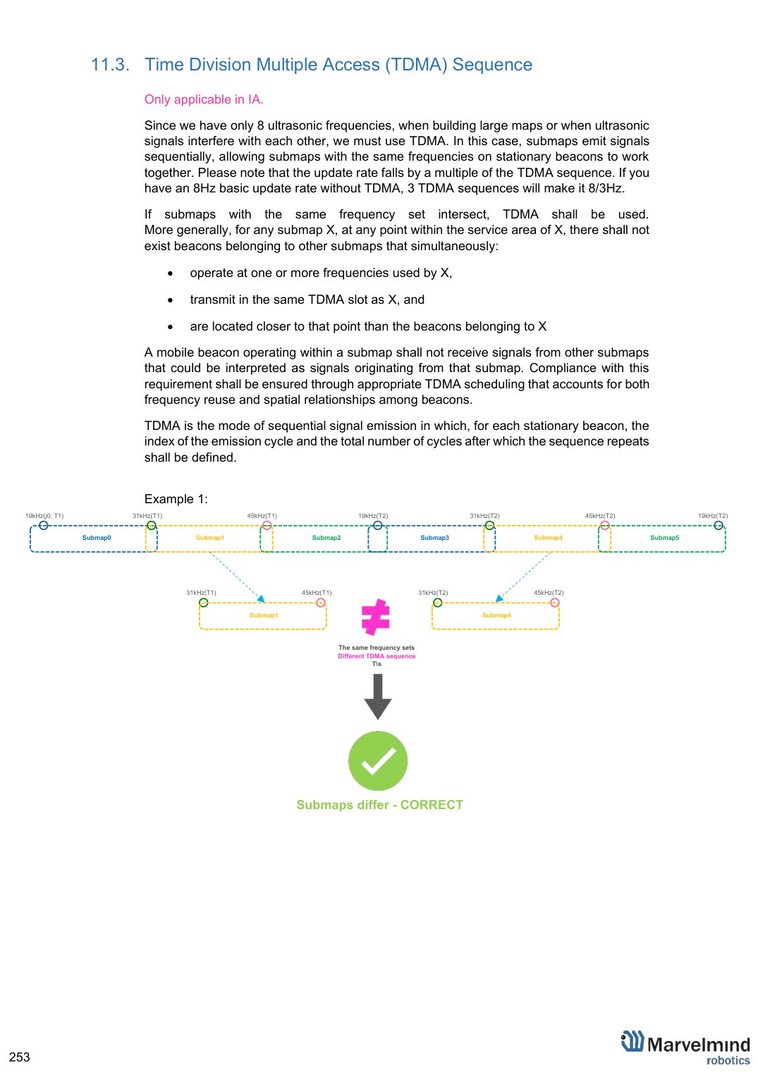
Since we have only 8 ultrasonic frequencies, when building large maps or when ultrasonic signals interfere with each other, we must use TDMA. In this case, submaps emit signals sequentially, allowing submaps with the same frequencies on stationary beacons to work together. Please note that the update rate falls by a multiple of the TDMA sequence. If you have an 8 Hz basic update rate without TDMA, 3 TDMA sequences will make it 8/3 Hz.
If submaps with the same frequency set intersect, TDMA shall be used.
More generally, for any submap X, at any point within the service area of X, there shall not exist beacons belonging to other submaps that simultaneously:
- operate at one or more frequencies used by X,
- transmit in the same TDMA slot as X, and
- are located closer to that point than the beacons belonging to X
A mobile beacon operating within a submap shall not receive signals from other submaps that could be interpreted as signals originating from that submap. Compliance with this requirement shall be ensured through appropriate TDMA scheduling that accounts for both frequency reuse and spatial relationships among beacons.
TDMA is the mode of sequential signal emission in which, for each stationary beacon, the index of the emission cycle and the total number of cycles after which the sequence repeats shall be defined.
Example 1:
For example, a 100×100 meter map in an open area consists of 55 submaps; the vertical rows of submaps are identical but operate in different TDMA loops. In this example, we used different colors for every TDMA position in sequence. TDMA 1(red) submaps emit first, TDMA 2(green) submaps emit second, TDMA 3(blue) submaps emit third:
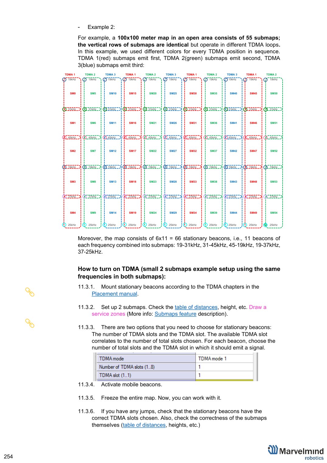
Moreover, the map consists of 6×11 = 66 stationary beacons, i.e., 11 beacons of each frequency combined into submaps: 19-31 kHz, 31-45 kHz, 45-19 kHz, 19-37 kHz, 37-25 kHz.
How to turn on TDMA (small 2 submaps example setup using the same frequencies in both submaps):
 Mount stationary beacons according to the TDMA chapters in the Placement manual.
 Set up 2 submaps. Check the table of distances, height, etc. Draw a service zones (More info: Submaps feature description).
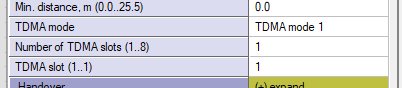 There are two options that you need to choose for stationary beacons: The number of TDMA slots and the TDMA slot. The available TDMA slot correlates to the number of total slots chosen. For each beacon, choose the number of total slots and the TDMA slot in which it should emit a signal.
Activate mobile beacons.
Freeze the entire map. Now, you can work with it.
If you have any jumps, check that the stationary beacons have the correct TDMA slots chosen. Also, check the correctness of the submaps themselves (table of distances, heights, etc.)
Increasing Update Rate
The update frequency is affected by 2 main parameters:
1) Radio profiles
2) Room dimensions (tracking areas)
If you need to tune the update rate of tracking, do the following:
1) Radio profiles:
There are 3 radio profiles available: 38 kbps, 153 kbps, 500 kbps:
38 kbps is the slowest but can cover a greater distance
153 kbps – average speed, overcomes the average distance (default)
500 kbps is the fastest but works at a shorter distance
Accordingly, to increase the update rate, we recommend switching to 500 kbps.
How to:
In the settings bar of each system device (including modem), change the Radio profile parameter to 500 kbps (or any you need). It is situated on the right side of the Dashboard screen.
Tip: Change the beacons’ profile before the modems to avoid losing your beacons. It allows you to do it remotely
2) Room dimensions (tracking areas)
The update rate also has a linear dependence on tracking distance (distance between the stationary and mobile beacon):
Longer distance – lower update rate
Smaller distance – higher update rate
If you have a room 10x10m, change the maximum distance setting. This will limit the system to the maximum measurement distance.
How to:
Go to the submap settings (click on the submap icon)
Change maximum distance value in meters (20 is a default)
Tip: Do not enter a very small value; use a 1-2 meter margin. Also, do not use 20 meters if you have a small tracking area. Tune carefully
Learn more here: How to increase location update rate?
Reducing Location Update Latency
The exact latency depends on many factors:
- IA or NIA
- From the modem or the beacon
- IMU sensor fusion or regular ultrasonic only
- Radio profile
- Realized update rate
- Any averaging or Real-time player, enabled or not
The range is:
~ 12 ms for data from a mobile beacon via USB with IMU fusion enabled and not averaging at all
~ 150 ms with 30m-submap and update rate in ultrasonic of 7 Hz and not averaging
~ 2 seconds with the same settings as in (b), but Real-Time Player with settings 16, i.e., it takes into account up to 16 previous readings before giving out the new one
 What affects delay:
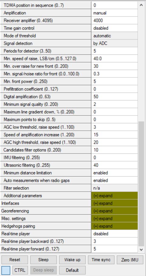
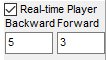
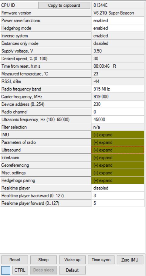 Real-Time Player in the Dashboard (For NIA)
Real Time Player in the hedge (For IA)
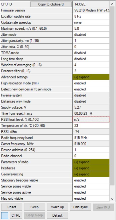 Window of averaging and Distance filter settings in modem (For NIA)
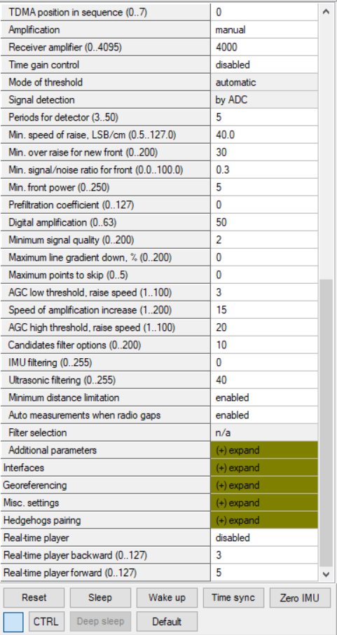 Prefiltration coefficient and Ultrasonic filtering settings in hedge (For IA)
 How to decrease latency:
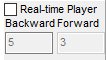 Turn off the Real-Time Player (works for IA and NIA)
Change the Window of averaging and Distance filter settings value to 0 (For NIA):
Choose Modem -> Window of averaging (in the right tab) -> Enter 0 value
Choose Modem -> Distance filter (in the right tab) -> Enter 0 value
Change the Prefiltration coefficient and Ultrasonic filtering settings value to 0 (For IA):
Choose your mobile beacon. Go to Ultrasound -> Prefiltration coefficient -> Enter 0 value
Choose your mobile beacon. Go to Ultrasound -> Ultrasonic filtering -> Enter 0 value
Complete. Latency reduced
Learn more here: How to increase location update rate?
How to Place Beacons
Avoid placing beacons on long sound-conducting objects
This is very rare but may happen under some exceptional circumstances.
The best practice is to place beacons (stationary and mobile) in places that would not result in the transfer of ultrasound energy from the beacon’s board/case directly to the place it is attached via a medium other than air. For example, solid attachment of a beacon to a long horizontal metal tube may result in the following:
- Sound emitted from the beacon propagates directly to the metal tube.
- Propagation losses inside metal are much smaller than in the air. Moreover, the tube may act as a low-loss waveguide.
- If the tube is solid enough and long enough, there may be an unusual effect where the receiving beacon receives the signal sooner than expected, i.e., sooner than the distance divided by the speed of sound in the air. That happens because the speed of sound in metal is much higher than the speed of sound in the air. The ultrasound signal may even look stronger than the actual signal propagated through the air due to the lower amount of losses of ultrasonic in metal than in the air.
- It is good practice to place beacons on something relatively soft or something that does not conduct sound.
Place beacons in a way that provides the proper ultrasonic coverage. One beacon must be in the line of sight of at least two beacons. Try to locate them under ceilings to avoid shadows, walls, etc.
- Optimal settings for stationary beacons in small and big rooms.
- Use 30-50 ultrasonic pulses for larger places and the default 5 pulses for smaller places.
- Optimal settings for noisy environments.
There are several ways to reduce impact:
- Mobile beacons can be placed close to the noise source without harm, but stationary beacons should be placed further from the noise because they are receiving the ultrasound. In contrast, the mobile beacon is emitting the ultrasound
Learn more about placing the beacons here: How to increase accuracy of precise indoor positioning system
Using the Oscilloscope
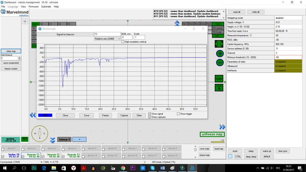
Echo
External noises look similarly. Thus, choose the ultrasonic threshold below this value, for example, -500 to -2000
Type the reference beacon number and press Enter
Choose the beacon to test
Ultrasonic signal front
Trigger (red line)
Emittion counter
Proper Ultrasonic Signal Detection
 This chapter is mostly related to HW v4.9 beacons. Super-Beacons Industrial Super-Beacons have high-power digital microphones for noise filtering and proper signal detection. Anyway, if you have problems with signal detection, read this chapter, no matter which beacons you use
These recommendations are suitable only for NIA
Marvelmind Indoor Navigation System uses proprietary multi-frequency for ultrasonic signals and employs additional filtering to combat external noise. This also makes the system relatively immune against the “usual suspects.” However, if the external noise is too strong, its source is too close, or it’s emitting a solid signal on frequencies close to 19, 25, 31, 37, 45 kHz, or white noise, the system functionality can be affected.
When external noise is high, identify the source. Usual sources include:
Ultrasonic-based volume or movement detection alarm systems
Other robots using ultrasonic
Parktronics
Sources of very strong white or impulse noise (air guns, air press, cutters, vacuum cleaner, etc.)
Rotors of drones/copters
The best things to do in this case:
Identify the beacons that are affected. Usually, they are those that are the closest to the source of noise. Try to reposition them
Manually reduce the gain of the affected stationary beacons so that the signal from the mobile beacon would have a 1000-1800 amplitude. That would give the best signal-to-noise ratio. Don’t make the gain too high. The noise will be amplified, but the desired signal will be saturated, and the signal-to-noise ratio will be poor
Input distances between beacons manually. More information – Table of distances
The gain settings may be very non-linear. There is almost no change from 4000 to 3000. But around 2500, the gain starts reducing very quickly (1200 for some HW versions). By setting the gain manually, it is possible to find the optimal gain to obtain the highest signal-to-noise ratio so the system can work even in very challenging external conditions.
When the map is formed, only the mobile beacon emits noise, whereas stationary beacons do not. Thus, it does not matter how close the mobile beacon is to the source of the noise. However, it matters how close the stationary beacons are to those sources. Select the positions of the stationary beacons accordingly-place them further away from the noise sources.
System Accuracy Evaluation
Accuracy of distance measurement:
- Marvelmind navigation system can measure distances between beacons with an accuracy of +/- 2 cm if the correct ultrasound speed is used.
- The ultrasound speed depends on temperature, pressure, and humidity. Other factors have an insignificant effect.
- The main factor is temperature. In the temperature range of -20…+50 °C, the speed of ultrasound changes to about 0.6 m/ (s* °C). It gives a distance error of about (0.6 / 340) *100% ~ 0.17%/ °C. So, caused by incorrect temperature setting, the absolute error of distance measurement is 0.17% of the real distance between beacons. For example, a distance of 30 meters and 5 °C error gives 0.85%*30 ~ 0.25 meters’ error. Marvelmind system allows the air temperature to be set up in the system settings.
Accuracy of position measurement:
- Marvelmind system uses a trilateration algorithm to calculate position by distances. The inaccuracy of position calculation is related to the inaccuracy of distance measurement and the geometry of the relative location of stationary and mobile beacons
- Basic
 trilateration formulas are given in this article: Trilateration (Wikipedia)
 - As you see, the position of mobile beacons X, Y, and Z is calculated from the positions of 3 stationary beacons, which are set by values of d, i, j. One of the beacons was shifted to the (0,0) position to simplify the formulas in the article. In formulas for X and Y, we see d and j as denominators. This means that with low values of d and j, a slight error of this value can cause a significant position error
- Please see the picture of the beacons in the article – in more simple words, it means that if one of three beacons is close to the line connecting the other two beacons, it gives increased inaccuracy of locating mobile beacon
 trilateration formulas are given in this article:
 For example:
assume d= 10, i= 5, j= 0.1, r1= 7, r2= 7, r3= 4.8
We get x= 5, y= 2.4375, z = 4.25
If we suppose that j=0.101 (0.1 cm error), we receive x= 5, y= -0.06, z= 4.89
You see a huge Y error
Another example for Z. Assume a mobile beacon is relatively close to a plane of stationary beacons:
d= 8, i= 4, j= 6, r1= 5.02, r2= 5.02, r3= 3.01
This gives X=4, Y= 3.01169, Z= 0.36
If we suppose r3= 3.0 (1 cm error), we receive X=4, Y= 3.016, Z= 0.44. Error on Z is about 8 cm
Also, with r1= 5, r2= 5, r3= 3, Z will be 0. As you see, a low change in distances causes a significant change in the Z value near the plane.
Learn more about accuracy here: Absolute vs. relative accuracy
Calibration of the accelerometer
To calibrate an accelerometer on your beacon with IMU, you can do the following steps:
- Connect the mobile beacon via USB to the Dashboard
- Make sure that the beacon has IMU on board: open the View / Accelerometer menu and view/gyro data. In the presence of IMU graphics in these windows should display the angular velocity and acceleration when moving the mobile beacon (turn it in hands).
Close the window of the accelerometer and gyro data.  Open the calibration window: View / calibrate the accelerometer
- When calibrating, it measures the data of the free fall (gravity of the Earth) corresponding to each of the three axes X, Y, Z. The initial ones from these calculations remember the correction shifts indicated in the table as "Zero" and the correction factors indicated as "K"
- The switch at the right bottom of the window should be in the AutoFill position
- Before starting the calibration, click the Reset button at the top of the window – zeroing the current calibration results
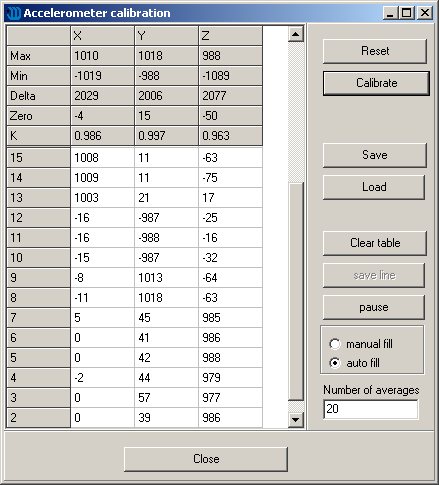 Open the calibration window: View / calibrate the accelerometer
To calibrate: slowly, without jerking, manually turn the beacon in each of the 6 positions and keep it still for 1-2 seconds:
The starting position – the beacon lies on the table; the antenna is pointing upwards (calibration Z +)
The beacon is turned upside down, the antenna pointing down (calibration Z-)
The beacon is on the end, the sensor RX1 is pointing towards the table (calibration Y +)
The beacon rests on the end, and the RX3 sensor points toward the table (calibration Y-)
The beacon rests on the end, the RX2 sensor is directed towards the table (calibration X +). In order not to interfere with the USB connector, the beacon can be placed on the edge of the table so that the cable hangs down
The beacon rests on the end, and the RX5 sensor points toward the table (calibration X-)
- In each measurement, the accelerometer’s readings are corrected by Zero and K.
At the end of the measurement of 6 points 7.1 … 7.6, in the serviceable accelerometer Zero should be close to zero, and K close to 1, see the screenshot.
If not – check if you forgot any of the points 7.1 … 7.6. - To save the results, click Calibrate.
Settings to Obtain Correct North Direction
In some cases, obtaining a correct north orientation of the map for NMEA output from the Marvelmind system is necessary. For example, when using a Marvelmind mobile beacon as the navigation data source for Pixhawk installed on a copter, the correct north is required for correct yaw control of the copter. The Marvelmind system cannot determine north automatically, so the user should make corrections after building and freezing the map. It can be done in one of two ways:
Option 1
- Rotate the Marvelmind map using the dashboard, as shown in the screenshot below
 You can also view the help video
 Rotate the Marvelmind map using the dashboard, as shown in the screenshot below
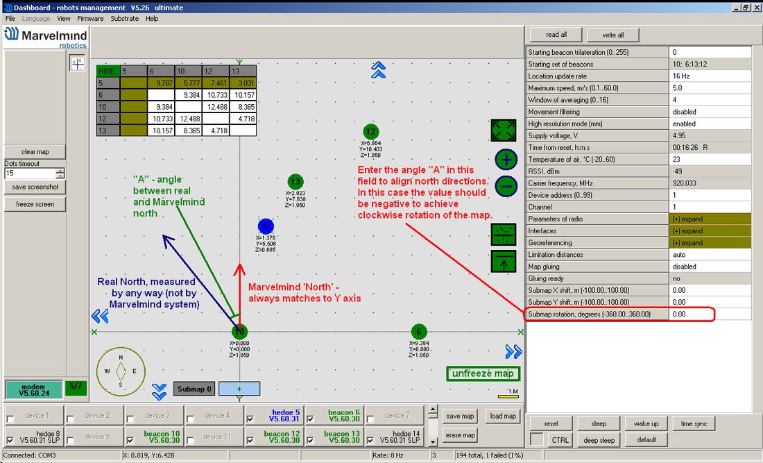 You can also view the
 Option 2
 Enter the angle correction (the angle shown in the screenshot) on the Pixhawk side from the Mission Planner of APM Planner
Refer to the parameter "BCN_ORIENT_YAW". Here is the link to ArduPilot
Marvelmind API
The Marvelmind API library is used by the Marvelmind Dashboard software and provides an interface to the user’s software. API is coming as a dynamic-link library (DLL) for MS Windows and a shared library for Linux (x86 and ARM platforms). The API connects to the modem via USB (virtual serial port) and implements the communication protocol with the modem.
In addition to the API library, the software package includes C example software, which was used for testing of the API and includes calls of all API functions.
The example can be used as a basis for developing a user’s software and for porting API library interface (file ‘marvelmind_api.c’) to other programming languages.
For details check the links below:
- Marvelmind interfaces (Chapter 10)
- GitHub
Tested on:
1. MS Windows 10; CPU: Intel Core i5
2. Ubuntu 20.04; CPU: Intel Core i5
3. Raspbian (2018-11-13-raspbian-stretch-full); Platform: Raspberry Pi 3 Model B+
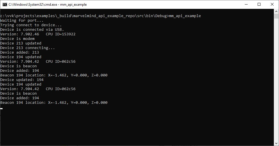
Figure 1. Example of a connection to Marvelmind API via USB
Communication of Pixhawk with Marvelmind Mobile Beacon
 The Marvelmind mobile beacon can be connected to Pixhawk (and to any other hardware or software that inputs GPS according to the NMEA0183 protocol). It can send GPS data via UART and USB (virtual UART) interfaces. For further explanation, please check out the following documents: PixHawk and Marvelmind Integration Manual and Marvelmind and PX4 integration.
Sending Path to Robot

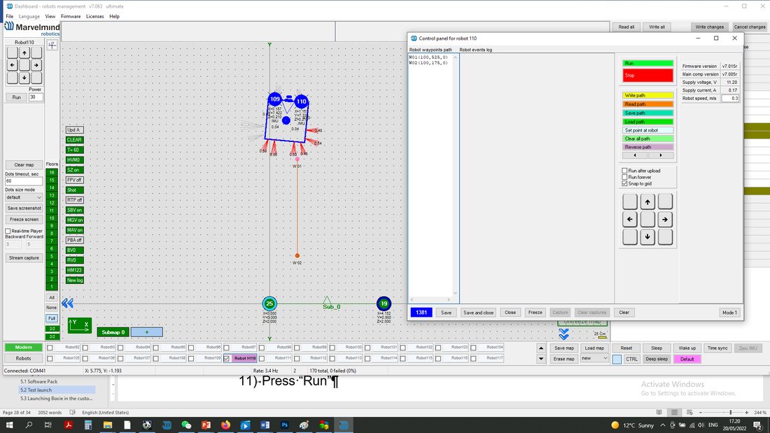 You can send the path for your robot via Dashboard
Check our help video.
- The dashboard sends a request to the modem via USB.
- The procedure for sending these requests in the dashboard is shown on the second screenshot.
- This format of the request is described in section 8 of the modem protocol:
 Modem transmits data to the hedgehog via radio, using our proprietary protocol
- The hedgehog communicates with the robot via UART. Hedgehog sends data according to section 2.3.1 of this protocol
- The robot should confirm receiving data by response packet shown in section 2.3
- This communication on the robot side is implemented in the Arduino example on our site. As you can see in the protocol, the robot should not request the waypoints; the hedgehog will send the waypoints when they are transmitted from the dashboard. But the robot should confirm receiving each waypoint by this packet:
- [0x03,0x47,0x01,0x02,0x00, <2 bytes of checksum>]
 This format of the request is described in section 8 of the modem protocol:
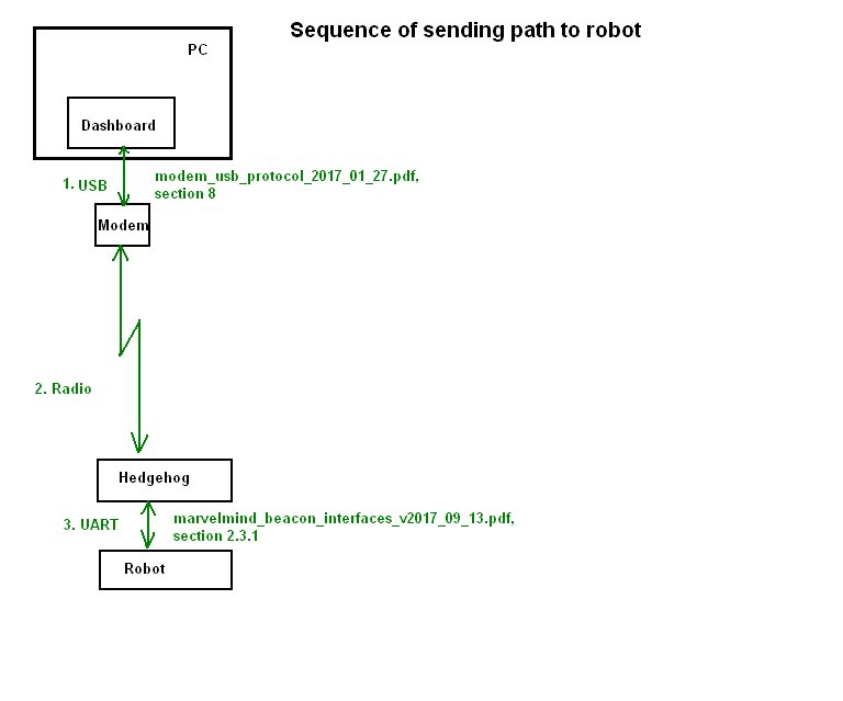 Modem transmits data to the hedgehog via radio, using our
 Learn more about Robot Boxie in the Marvelmind Boxie Operating Manual
How to send a path:
- Set up the Marvelmind Indoor “GPS” system
 Turn on Boxie and wait for 1 minute
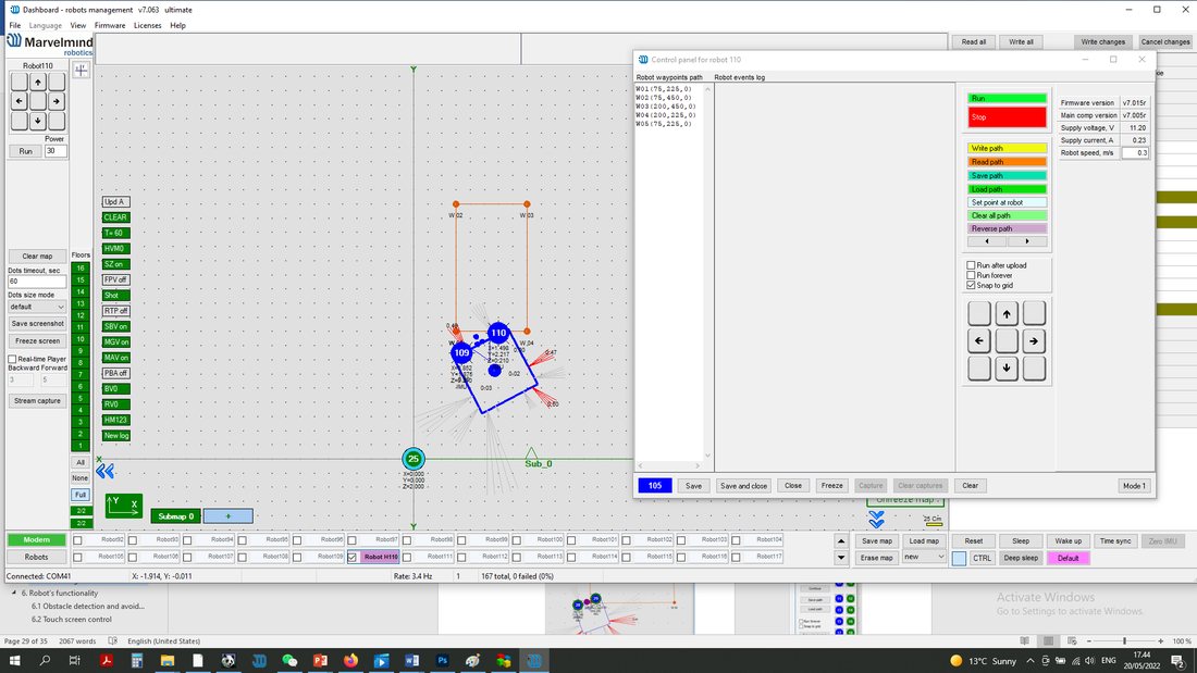
- Configurate paths and points (Use Shift+Left mouse button click to create a point, click on point – to remove):
- Press “Run”. Robot will follow the path that you draw:
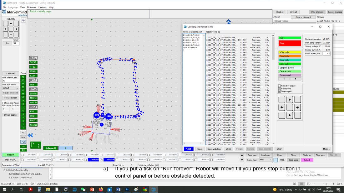
- If you put a tick on “Run forever”. Robot will move till you press stop button in control panel or before obstacle detected:
 Proper Ultrasonic Coverage
 Turn on Boxie and wait for 1 minute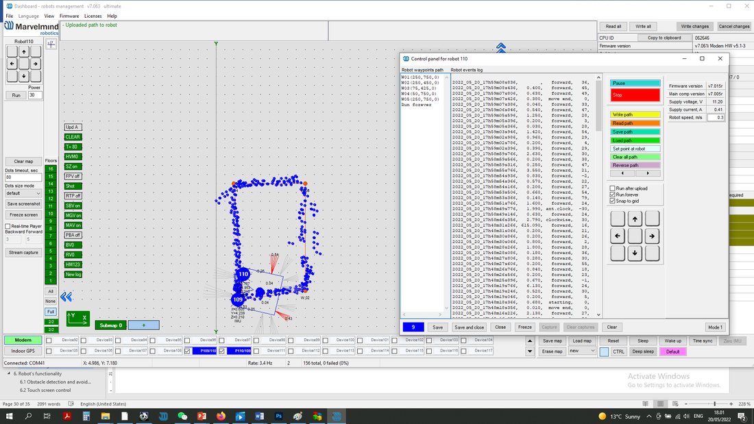
 Configurate paths and points (Use Shift+Left mouse button click to create a point, click on point – to remove):
  Proper Ultrasonic Coverage
The most critical requirement for the system to work well is to have proper ultrasonic coverage.
Each sensor has an ultrasonic beam of ~90 degrees. Outside of that range, the emitting power and sensitivity drop quite rapidly. The signal is highly attenuated from the left, right, or back of the ultrasonic sensor. Thus, it is crucial to provide proper ultrasonic coverage for the area where the robot will be moving.
- It is also very important to provide proper ultrasonic coverage to the stationary beacons when the map is being formed
- Mobile beacon (“hedgehog” or “hedge”) is designed to be placed horizontally
- The mobile beacon has four horizontal and one vertical sensor, each covering its own sector. Together, they cover 360 degrees horizontally and 180 degrees in the upper hemisphere. The lower hemisphere is highly attenuated, so don’t expect ultrasonic coverage in that area
- If the stationary beacons are above the mobile beacon, it is advised that the mobile beacon be placed as high as possible on the robot. This minimizes shadows from other objects, people, etc.
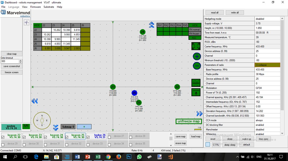

- An example of proper positioning of the mobile beacon can be found here
- The beacon is placed horizontally and above other objects that can cast a shadow on the stationary beacons
- Keep the radio signal’s strength under control
- The RSSI (Dashboard => right menu) of any beacon/modem must not be higher than -25 dBm. Otherwise, the system may malfunction
- It is recommended the distance between the modem and beacons be no less than 0.5-1m. Beacons can be placed as close to each other as needed. If a beacon is exceptionally close to the modem, disconnect the antenna from the beacon. Monitor the Received Signal Strength Indicator (RSSI). It must be in the range of -25 to -70 dBm. An RSSI of less than -70 dBm will also work, but packet losses may occur. The quality of the radio connection also depends on external interference because the used band is ISM (either 915 MHz or 433 MHz), and there are numerous co-existing systems.
- Use 30 – 50 periods (pulses) in settings instead of the default 5. Select:
 Ultrasound settings => Number of periods
 - When you have large errors in position estimation (more than a 1m inaccuracy), use the embedded Oscilloscope on Dashboard => View to determine which stationary beacon is jammed
- Reduce the gain of the ultrasonic manually depending on your system
Enabling and Disabling Specific Transducers
 An example of proper positioning of the mobile beacon can be found
 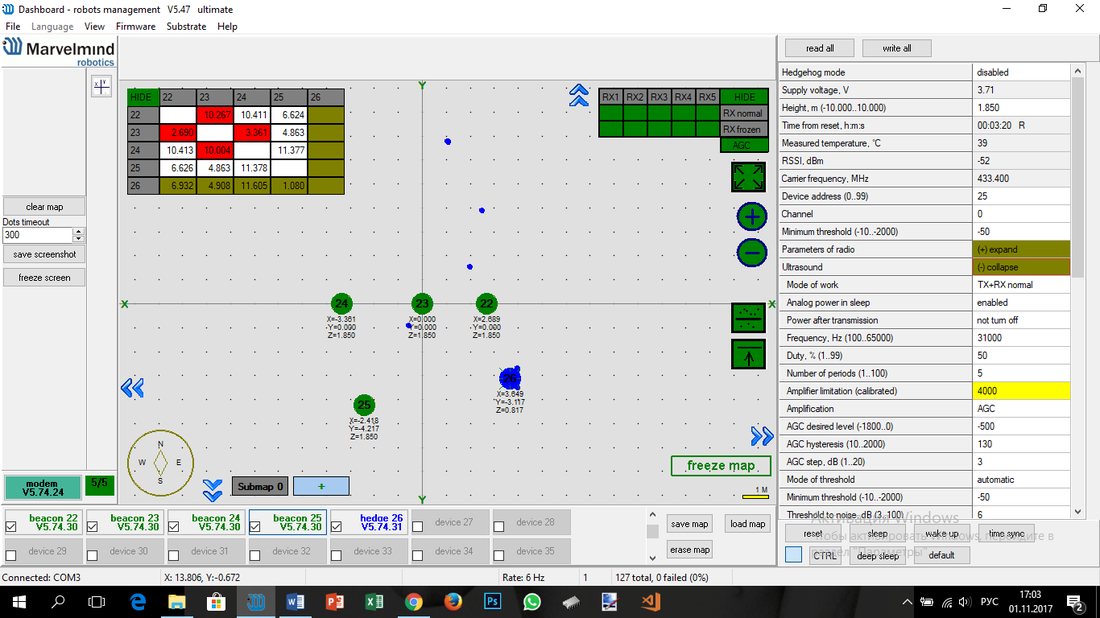 Ultrasound settings => Number of periods
 To increase tracking accuracy and prevent false signals we recommend disabling transducers on a beacon which are redundant and emit signal into walls which causes reflections or where hedgehog won’t be (not including setting up a submap step; begin disabling transducers after you set up a submap).
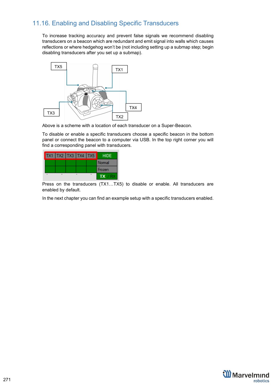
Above is a scheme with a location of each transducer on a Super-Beacon.
To disable or enable a specific transducers choose a specific beacon in the bottom panel or connect the beacon to a computer via USB. In the top right corner you will find a corresponding panel with transducers.
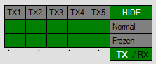
Press on the transducers (TX1…TX5) to disable or enable. All transducers are enabled by default.
In the next chapter you can find an example setup with a specific transducers enabled.
Transducers Setup: Example for 2D and Mobile Beacon
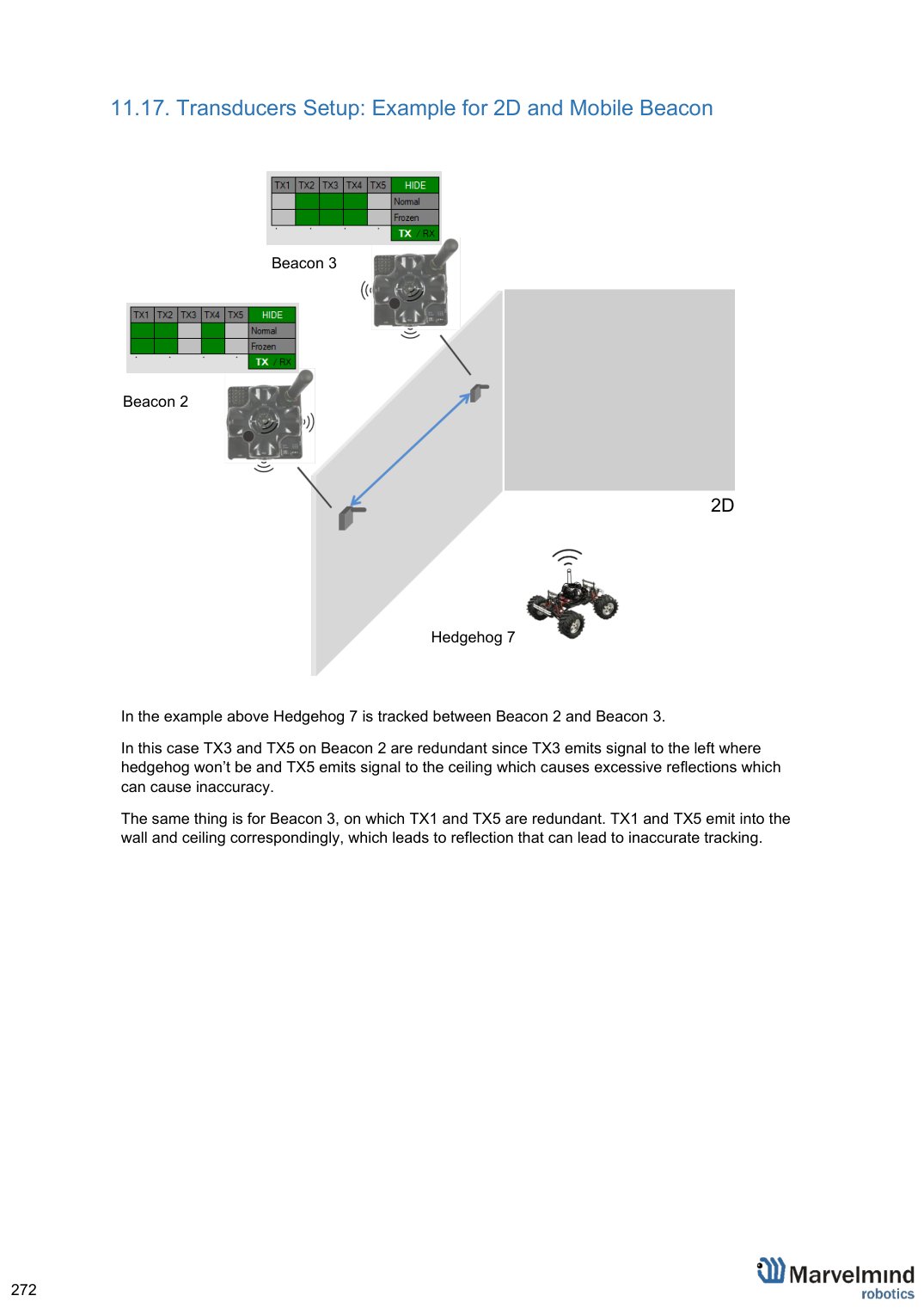
In the example above Hedgehog 7 is tracked between Beacon 2 and Beacon 3.
In this case TX3 and TX5 on Beacon 2 are redundant since TX3 emits signal to the left where hedgehog won’t be and TX5 emits signal to the ceiling which causes excessive reflections which can cause inaccuracy.
The same thing is for Beacon 3, on which TX1 and TX5 are redundant. TX1 and TX5 emit into the wall and ceiling correspondingly, which leads to reflection that can lead to inaccurate tracking.
Powering Beacons
 Depending on the type of beacon, it may be an internal battery or an external USB power supply; for more details, check the comparison table
Battery lifetime depends on the mode of operation and can be varied between several days to several months (or more for special applications)
Learn more here: Power supply options for beacons
Power Supply and Leds
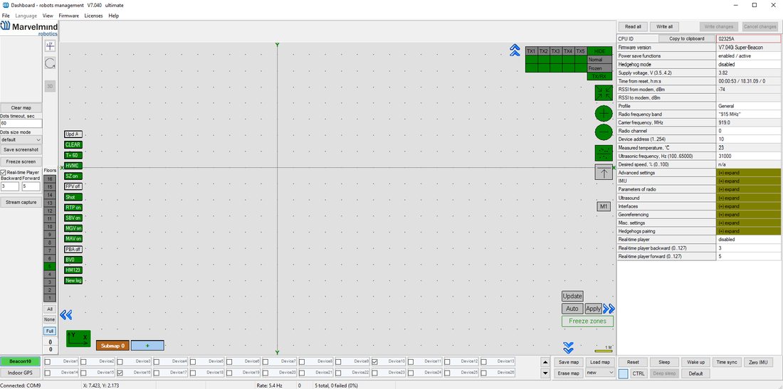
Status of charge:
- 4.1 V – 4.2 V – absolutely fully charged
 3.6 V – 4 V – good charged
- 3.2 V – 3.6 V – very low charge
- 3.2 V – fully discharged
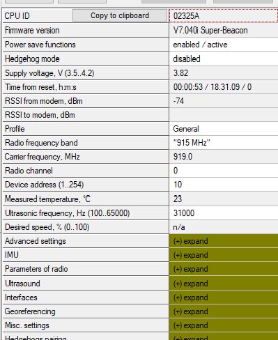 3.6 V – 4 V – good charged
Learn more here: Power supply options for beacons
Licenses How to Activate Licenses
Please note that we have different types of licenses for modems and beacons. If you need to activate the beacon’s license – connect the specific beacon to the Dashboard to choose a license for that beacon. Connect modem for modem’s licenses.
 We added the licenses system. Now, you can order some additional features. It is unavailable in the basic Dashboard version, but you can easily purchase it if necessary. You can see the list on Marvelmind.com -> Products
To order:
- Go to Marvelmind.com -> Products
- Choose features which you want to get (e.g., MMSW0001: 100 Hz NMEA0183)

- Make an order.
- Pay for the feature (via PayPal or other methods).
- Order the feature via the Dashboard by providing the device’s CPU ID or send us an email with the device’s CPU ID:
 Go to
Go to 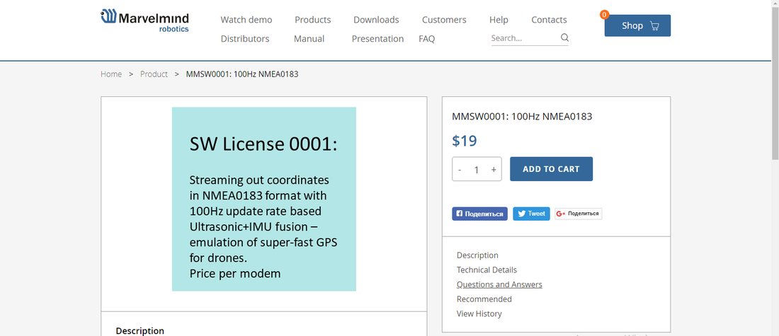
Open Dashboard SW
Connect the device you need to order a license to the Dashboard via USB
Go to Licenses → View/activate licenses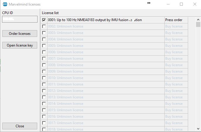
Choose the licenses that you have purchased.
Press Order licenses.
Dashboard will generate a text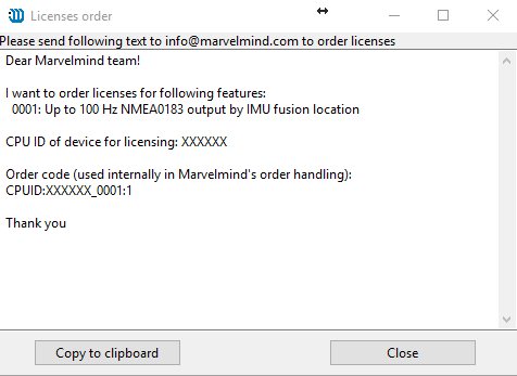
Send generated text to info@marvelmind.com
We will generate the license key and send it to you via email
Place the license key into the Dashboard/Licenses folder:
Connect the device to the Dashboard via USB
Go to Licenses → View/activate licenses
Choose "Open license key"
Choose the license file (be careful if you have licenses for multiple devices; check CPU ID carefully)
The features become activated in the Dashboard.
100 Hz NMEA0183 for Drones
This feature requires MMSW0001 license.
Only works only with Beacons HW v4.9-IMU.
Streaming out coordinates in NMEA0183 format with 100 Hz update rate based on Ultrasonic + IMU fusion – emulation of super-fast GPS for drones.
Description:
- Regular location update for the Indoor “GPS” system is based on ultrasonic only and shows a usual update rate in the range of 4-16 Hz per system. There is also Ultrasonic + IMU fusion data available, but it is in Marvelmind’s internal format, which is not regularly acceptable by devices compatible with NMEA0183 (native GPS format), for example, PixHawk and Ardupilot
- The feature is taking Ultrasonic + IMU fusion location data that is streamed out with 100 Hz update rate and converts to NMEA0183, thus, emulating super-fast GPS signal
- The feature works only with Beacons HW v4.9-IMU. Future support of Super-Beacons, Industrial Super-Beacons, is possible, but an exact roadmap has not been defined yet
Getting $GPHDT Heading Packet in NMEA0183
This feature requires MMSW0002 license.
This feature allows to get $GPHDT packet (heading) in NMEA0183.
Works with Paired Beacons configuration for Location + Direction. Check the Paired Beacons chapter.
Videos:
- Demo: Precise (±2 cm) Location + Direction Indoor
- SW feature demo: paired beacons – location + direction
Supported devices:
- Super-Beacon
- Beacon Mini-RX
- Industrial Super-Beacon
- Beacon Industrial-RX
UBX (u-blox) Protocol for PX4
This feature requires MMSW0003 license.
The feature allows a mobile Super-Beacon to stream out data using UBX (u-blox) protocol. It is used for PixHawk with PX4 stack. This feature also allows substituting a u-blox compass that may not work indoors with a signal from the Paired Beacons. PixHawk will believe that is getting direction data from u-blox compass via I2C.
Works only with Super-Beacon.
Check the Paired Beacons chapter.
Videos:
- Demo: Precise (±2 cm) Location + Direction Indoor
- SW feature demo: paired beacons – location + direction
Links:
- Communication of PixHawk with Marvelmind Mobile Beacon
- Drones
Advanced SW Pack
MMSW0005 – one of the most significant licenses for Marvelmind SW.
Learn more: SW Pack 7.0/7.1 Release Notes
In the previous version of SW (older than 7.200), when the license was activated, the version of SW changed from 7.0xx to 7.1xx.
From version 7.200 activated license shows in the Dashboard as “L”
If license MMSW0005 is activated for all devices, it shows L in the window capture of the Dashboard next to the version of Dashboard:

If the license is not activated for one or more beacons in a system, it will be reported in the right information window:
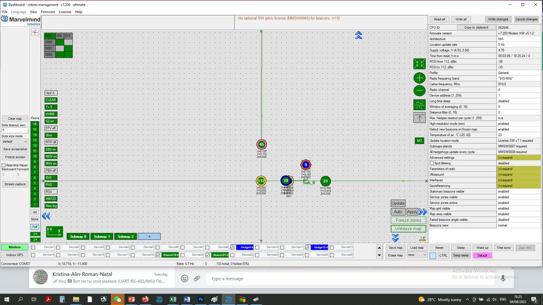
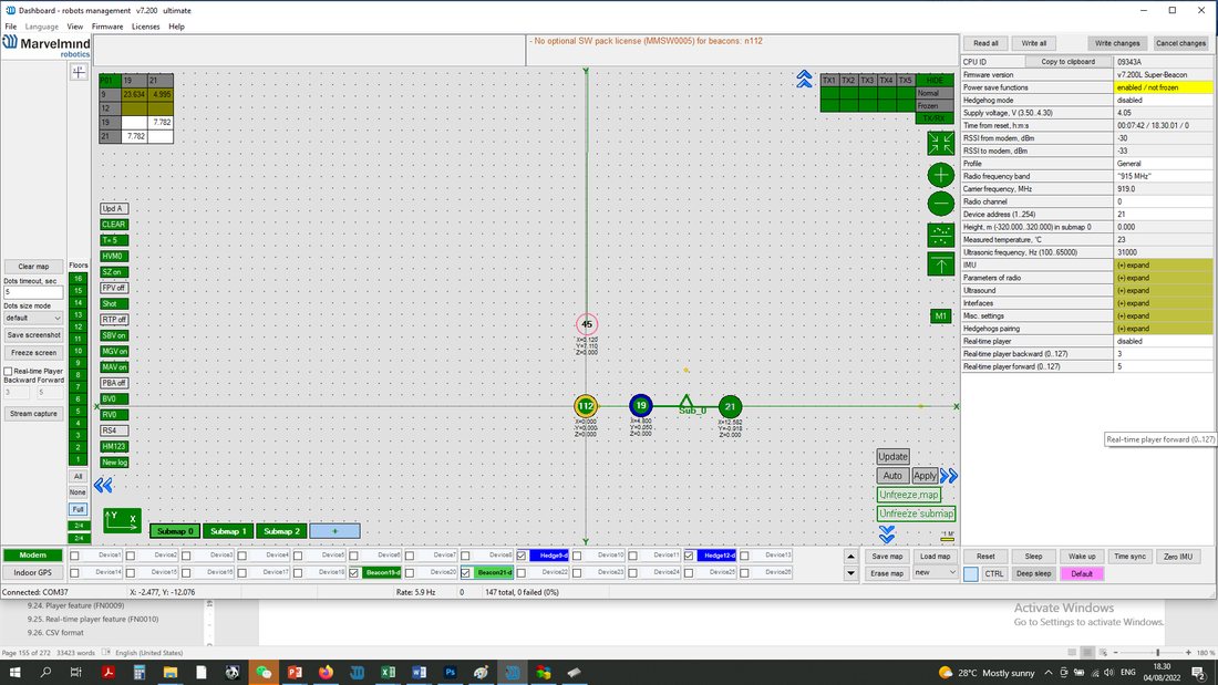
And “L” will be shown next to the version of firmware of each beacon with the activated license:
Geofencing Alarm
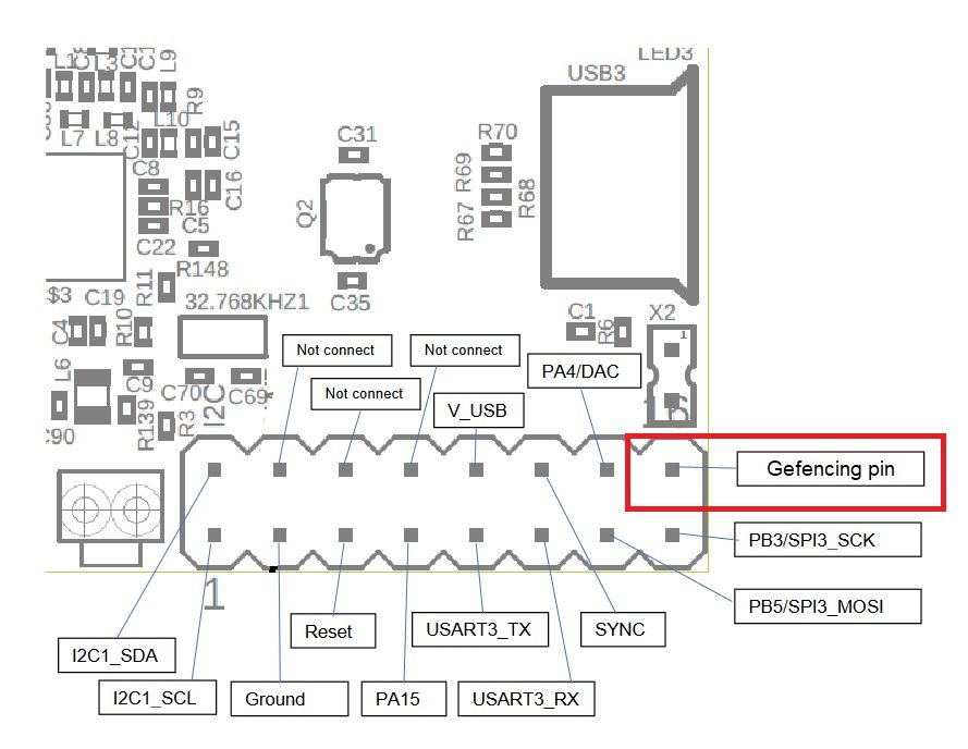
SW License MMSW006 activates support for a dedicated pin for geofencing zone violation. Instead of reading the stream of location data in the protocol, it is now possible to have just a pin from the 4X4 of Super-Beacon or pins on the modem or internal pins in the Mini-RX to be automatically switched to “0” or “1”, on every time reset, when the geofencing zone rules are violated.
Supported hardware:
- Super-Beacon
- Modem HW v5.1
- Mini-RX
Follow the instructions below to use this feature:
- Connect the alarm to your device according to the scheme:
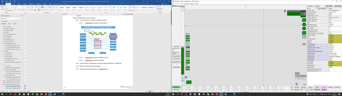
- Geofencing pin scheme for Super-Beacon (when license-activated SPI will not be available):
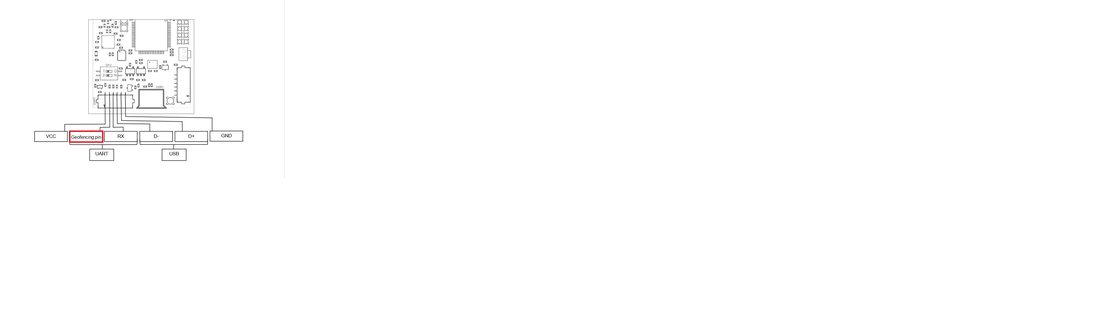
 Geofencing pin scheme for Modem HW v5.1:
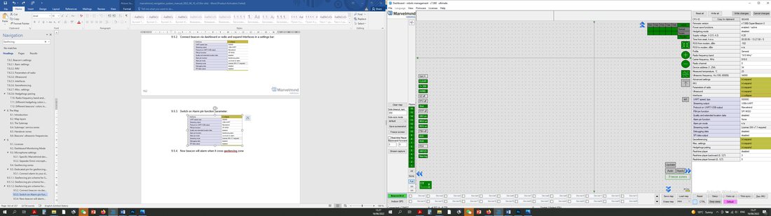
 Geofencing pin scheme for Mini-RX:
- Connect beacon via dashboard or radio and expand Interfaces in a settings bar:
- Switch on the Alarm pin function parameter:
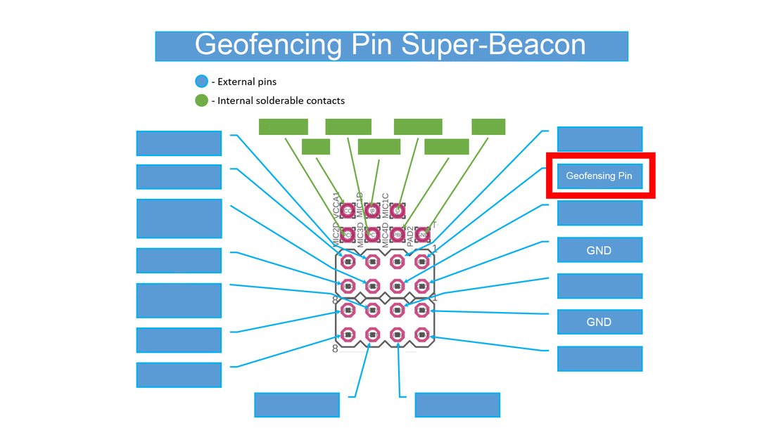 Geofencing pin scheme for Super-Beacon (when license-activated SPI will not be available):
 Geofencing pin scheme for Modem HW v5.1:
 Geofencing pin scheme for Mini-RX:
 Connect beacon via dashboard or radio and expand Interfaces in a settings bar: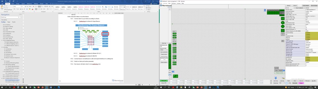
- Choose the needed alarm pin mode according to a bellow table:
|
|
|
|
|
|
|
|
|
- Geofencing alarm settings completed.
Islands Feature
To use the Islands Feature, a license MMSW0007 is needed, as well as Marvelmind SW from version 7.200 and the latest.
This feature allows you to make different submaps for each hedge.
How to do this (it’s an example with 2 submaps. 4 stationary beacons, and 2 mobile beacons):
- Awake all 4 stationary beacons (Click on it with the Left mouse button):
- Leave 2 of them on Submap0 and move another 2 on Submap1. You will get 2 separate submaps.
- Move submaps as you wish. Use CTRL and mouse roll to rotate Submap.
- Awake mobile beacons. It will appear on a map.
- If the license is activated correctly, you can select the “islands” mode with a selected modem and assign mobile beacons to submaps.
- Enable Submaps islands.
- When Submaps Islands mode is enabled, you can choose a submap for each beacon.
- Now mobile beacon 12 will work with Submap 1 and mobile beacon 9 will work with Submap 0.
- Freeze each submap and Freeze the map.
- Islands feature setup is completed.
All Hedgehogs Update Every Cycle
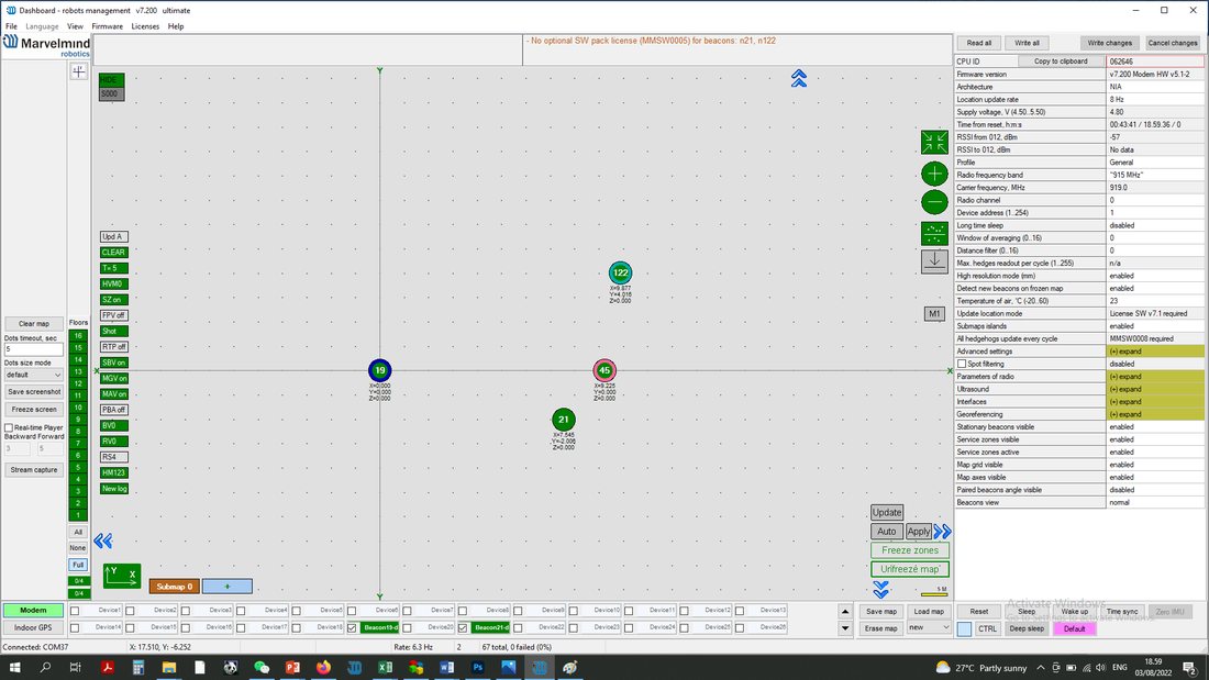 Awake all 4 stationary beacons (Click on it with the Left mouse button):
 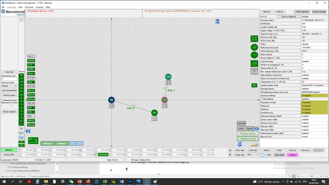 Leave 2 of them on Submap0 and move another 2 on Submap1. You will get 2 separate submaps.
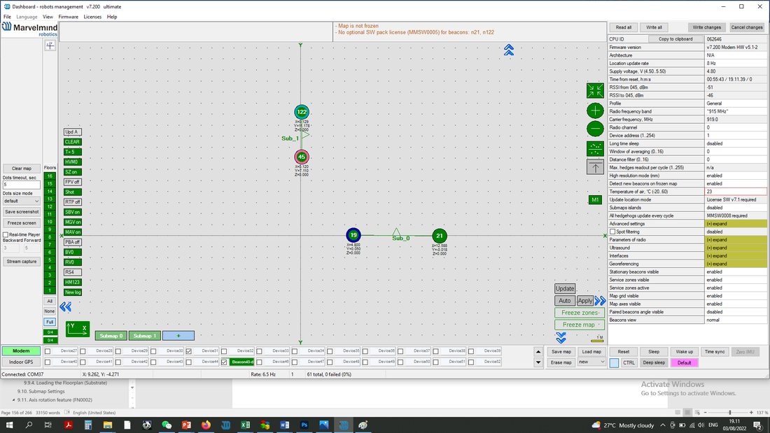 Move submaps as you wish. Use CTRL and mouse roll to rotate Submap.
 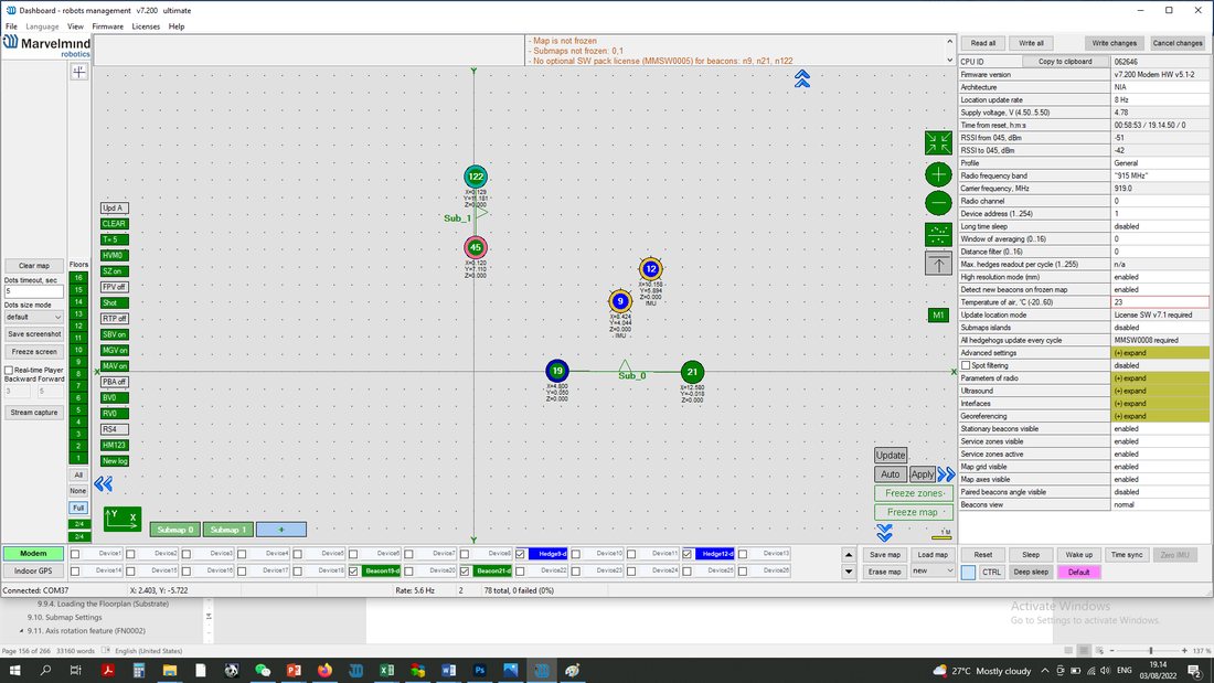 Awake mobile beacons. It will appear on a map.
 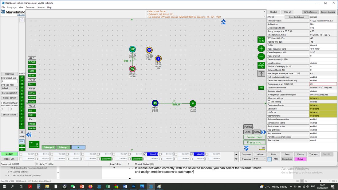 Enable Submaps islands.
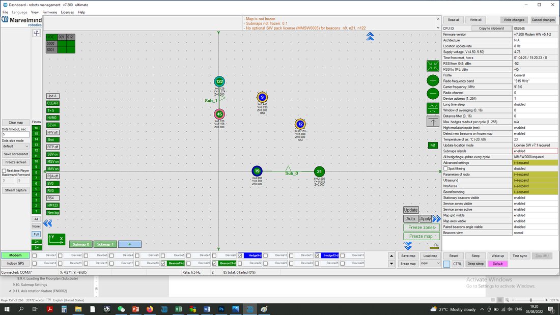 When Submaps Islands mode is enabled, you can choose a submap for each beacon.
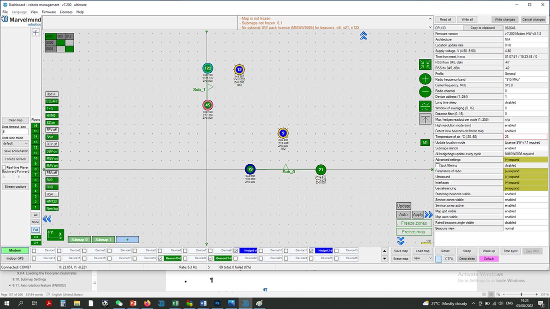 Now mobile beacon 12 will work with Submap 1 and mobile beacon 9 will work with Submap 0.
 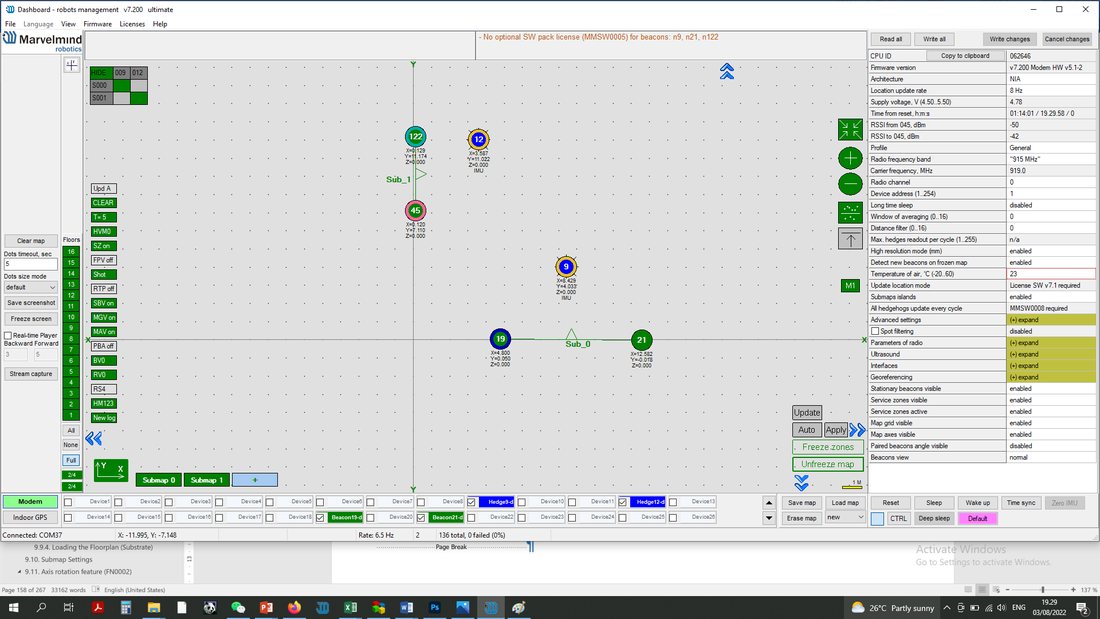 Freeze each submap and Freeze the map.
 To use the “All hedgehogs update every cycle” feature license, MMSW0004 (MF NIA) and MMSW0008 are needed, as well as Marvelmind SW from version 7.200 and the latest.
This feature emits all mobile beacons in MF NIA simultaneously (to increase the update rate in cases where it is known that they won’t interfere with each other).
How to use it:
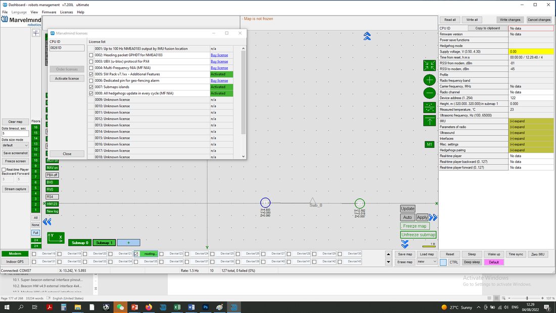
 Make sure that licenses
- Choose modem:
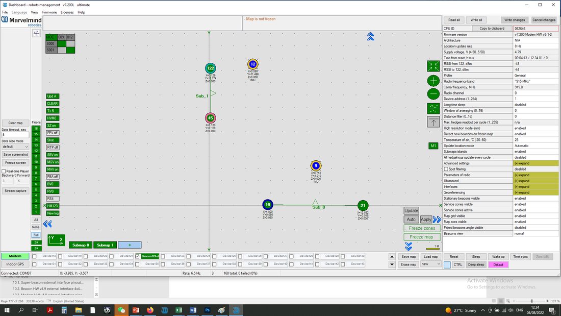
- Enable “All hedgehogs update every cycle” in the settings bar. Left mouse click on disabled (if feature switched off)
- Now all mobile beacons update every cycle.
Ultrasound + IMU Sensor Fusion
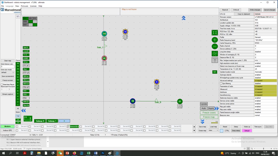 Enable “All hedgehogs update every cycle” in the settings bar. Left mouse click on disabled (if feature switched off)
This feature requires MMSW0009 license.
A typical location update rate of indoor positioning systems or GPS is ~8-16 Hz, which is enough for most industrial applications, but not for all.
A practical way to increase the location update rate to 100 Hz and more is to use IMU and ultrasound sensor fusion that combines the best of both sources of data: a very fast update rate and robustness of IMU and absolute coordinates and no drift of the ultrasound positioning system.
Typical application of the fast indoor positioning system with sensor fusion:
- Fast mobile objects: karting or quick industrial machinery
- Fast sports: half-pipe ski jumpers, indoor bike parks, BMX tracks, skate parks, etc.
More info:
- Fast indoor positioning system based on IMU sensor fusion
- Fast indoor positioning system based on IMU sensor fusion (Video)
Currently tested and supported in IA only. Support in NIA and MF NIA is coming in future. Additionally, tested and supported by Super-Beacon and Modem HW v5.1, other hardware may be supported on request.
RS485 Instead of Radio
This feature requires MMSW0010 license.
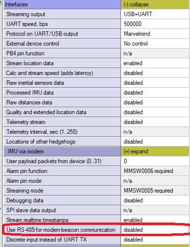
This feature allows connectivity between the Super-Modem and Stationary Industrial beacons via RS485 wired interface instead of the radio in an ISM band. It is beneficial when radio connectivity is either not available, subject to interference, or must be hidden.
Note: To enable RS485 mode, select the device in the Dashboard and open its settings: Configuration → Communication → RS485 Instead of Radio. See also: MMSW0010 license page for details.
Supported devices:
API for Manual Distance Measurement
This feature requires MMSW0011 license.
This feature allows you to manually measure distance from beacon to beacon based on the API command.
In regular use of the system, the operations are split between two distinct modes:
- Building the map of stationary beacons
- Using the map of stationary beacons for positioning mobile beacons
In mode 1, the system automatically and constantly builds a table of distances between the stationary beacons within a submap until the user freezes the submap or distances in the table of distances confirming that they are correct.
The API for Manual Distance Measurement enables manual measurement between beacon and any other beacon in the system. The feature assumes there are no submaps anymore. The distance can be measured from any beacon to any beacon.
Supported devices:
- Super-Beacon
- Industrial Super-Beacon-Plastic
- Beacon Industrial-RX
- Beacon Mini-RX
- Modem HW v5.1
- Super-Modem
Location Update Rate Boost
This feature requires MMSW0012 license.
The feature optimizes (minimizes) timing between the location updates. As a result, the location update rate is boosted by 20-100%, depending on the initial configuration: Marvelmind Indoor Positioning System location update rate and user data transfer rate table.
It is done for the expense of eliminating time slots normally occupied by advanced telemetry and data transfer. Thus, advanced telemetry (waking up new beacons while the map is already frozen, for example) or user payload data transfer is unavailable. After freezing the map, no changes to the configuration are possible. But as a result, a higher location update rate is achievable.
It is recommended to use all other recommendations along with the feature to achieve a truly high location update rate of 40+Hz for small submaps.
See for more details:
- How to increase the location update rate and reduce latency?
- Marvelmind Indoor Positioning System location update rate and user data transfer rate table
Supported devices:
- Super-Beacon
- Industrial Super-Beacon-Plastic
- Beacon Industrial-RX
- Beacon Mini-RX
- Modem HW v5.1
- Super-Modem
Supported architectures:
This feature requires MMSW0013 license.
This feature allows using a mobile beacon as a virtual pen and drawing track on a display or projector. It is possible to wipe or move the mobile beacon without a trail by turning the mobile beacon ~±90.
Supported devices:
- Super-Beacon
- Industrial Super-Beacon-Plastic
- Beacon Industrial-RX
- Beacon Mini-RX
- Omni-Microphone-IP67
- External Microphone-IP67
- Modem HW v5.1
- Super-Modem
Supported architecture:
Recommended configuration:
As infrastructure:
- 2 x Super-Beacon with different frequencies, for example, 31 kHz and 45 kHz placed on the wall above the screen
- 1 x Modem HW v5.1, as a controller connected to the Dashboard or computer
As a “virtual pen”:
- 1 x Super-Beacon with Omni-Microphone-IP67 (soldering not required) or
- 1 x Super-Beacon with External Microphone-IP67 (soldering required) or
- 1 x Mini-RX with Omni-Microphone-IP67 (soldering required) or
- 1 x Mini-RX with External Microphone-IP67 (soldering required)
An External Microphone-IP67 or Omni-Microphone-IP67 will be a “tip of the pen” for easy drawing.
It is recommended to use along with Location update rate boost for the highest update rate and the lowest – the most comfortable drawing.
See for more details:
- How to increase the location update rate and reduce latency?
- Marvelmind Indoor Positioning System location update rate and user data transfer rate table
Marvelmind API via UDP
This feature requires MMSW0014 license.
 Super-Modem also supports Marvelmind API via UDP. In future, the whole system will be available via TCP or UDP via Dashboard.
Link for the Marvelmind API chapter.
 See the complete instructions here (Chapter 10)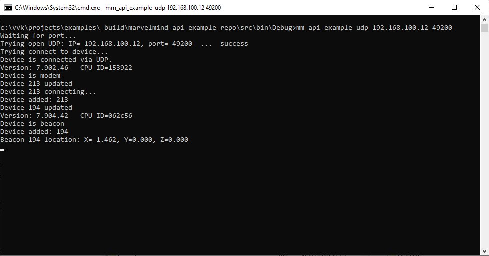
Automatic Submap Self-Calibration
The license MMSW0015 is required for this feature.
Submap periodically measures the distance between its beacons, compares it with manually entered by user reference distance, and calculates the calibration coefficient, which can be used for tracking in this and other submaps.
After receiving the coefficient from the reference submap, it will be sent to other submaps for more accurate tracking. There can be as many reference submaps as needed, in case if temperature in several reference submaps differs from each other. Non-reference submaps can be referred to as any reference submap.
Additionally, users can adjust self-calibration interval. Increasing its value will decrease the frequency of adjusting the coefficient, vice versa decreasing its value will increase the frequency of adjusting the coefficient but will load the system more.
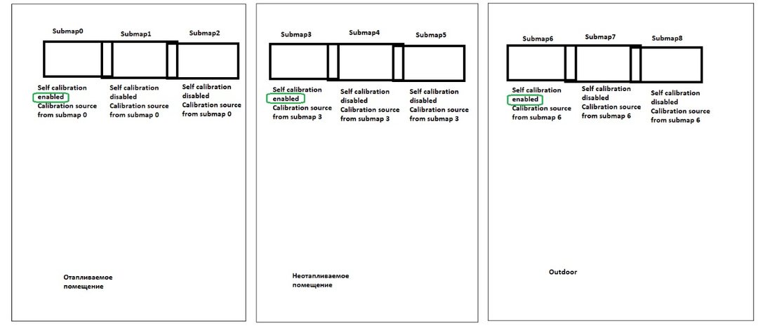
Figure 4. Absolute calibration based on reference submap 3
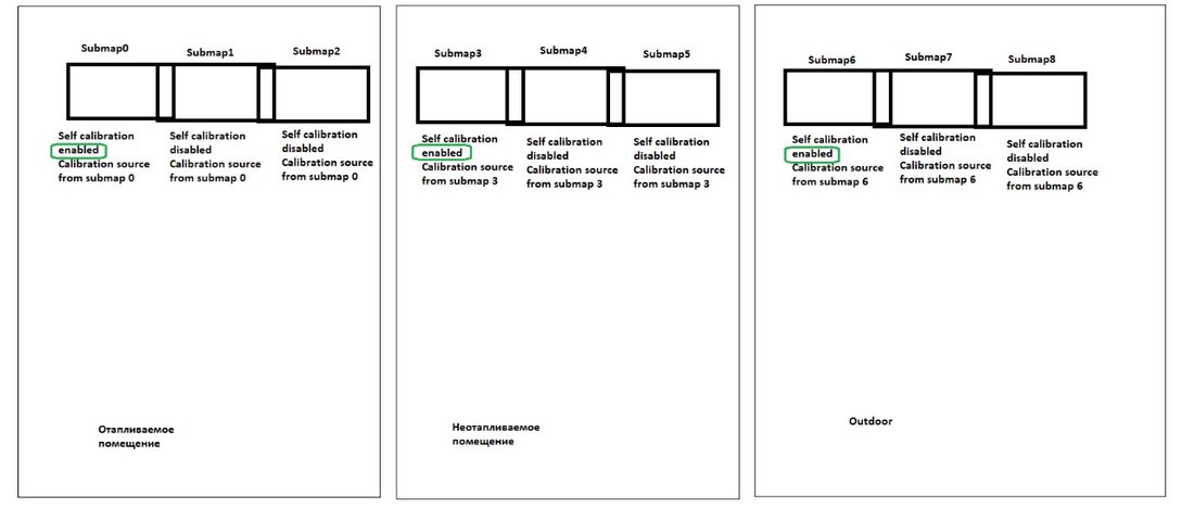
Figure 1. Absolute calibration based on reference submap 0
Below are instructions on how to enable this feature:
Enable the MMSW0015 license on a modem (one per submap)
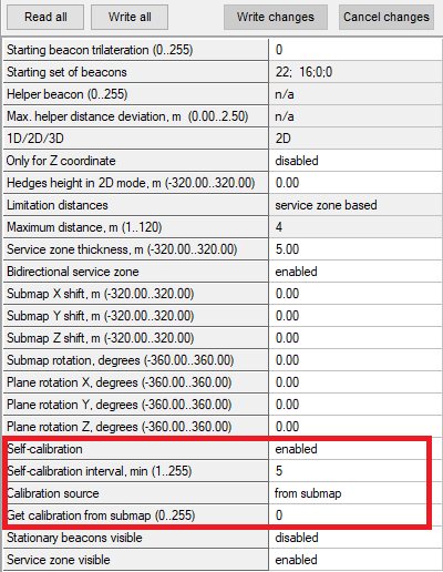 Select a reference submap and enable Self-calibration
For the reference submap, the “Get calibration from submap” value should be the number of a submap itself (ex. Ref. submap number – 0, “Get calibration from submap” = 0)
Change “Self-calibration interval” if necessary
Enter the absolute distance (physically measured distance) between the beacon pair in a reference submap
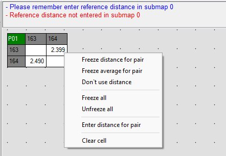
 The coefficient will be updated and ready for use
Select a non-reference submap, change “Calibration source” to “from submap,” and change the number to a number of a reference submap
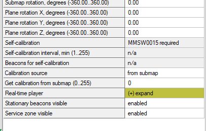
Now, submap 1 will be referred to an absolute distance coefficient in referenced submap 0. Any number of submaps can be referred to a referenced submap.
UDP Streaming
This feature requires MMSW0016 license.
This feature enables data streaming of data via UDP.
Supported devices:
- Super-Modem for native UDP streaming directly from the Super-Modem via UDP over Wi-Fi
- Modem HW v5.1 for streaming from the Dashboard via any IP, for example, Wi-Fi or Ethernet
More info: