
Dashboard menu and parameters
This chapter as a clean, readable HTML page.
The “Dashboard menu and parameters” chapter of the Operating Manual, reproduced as a real HTML page. Anything unclear? Open the original PDF of just this chapter (pages 125-159) (also pinned top-left). Hub: all chapters.
Dashboard General View
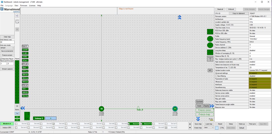
This picture shows the Dashboard’s general interface and items’ positions.
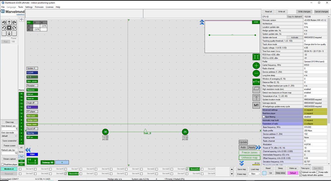
Modem/beacon’s quick control panel
Visualization window
Diagnostics Messages Window
The diagnostic messages window is an area where essential system messages appear. It may contain a lot of helpful information.
The Diagnostics window is placed at the top of the Dashboard.
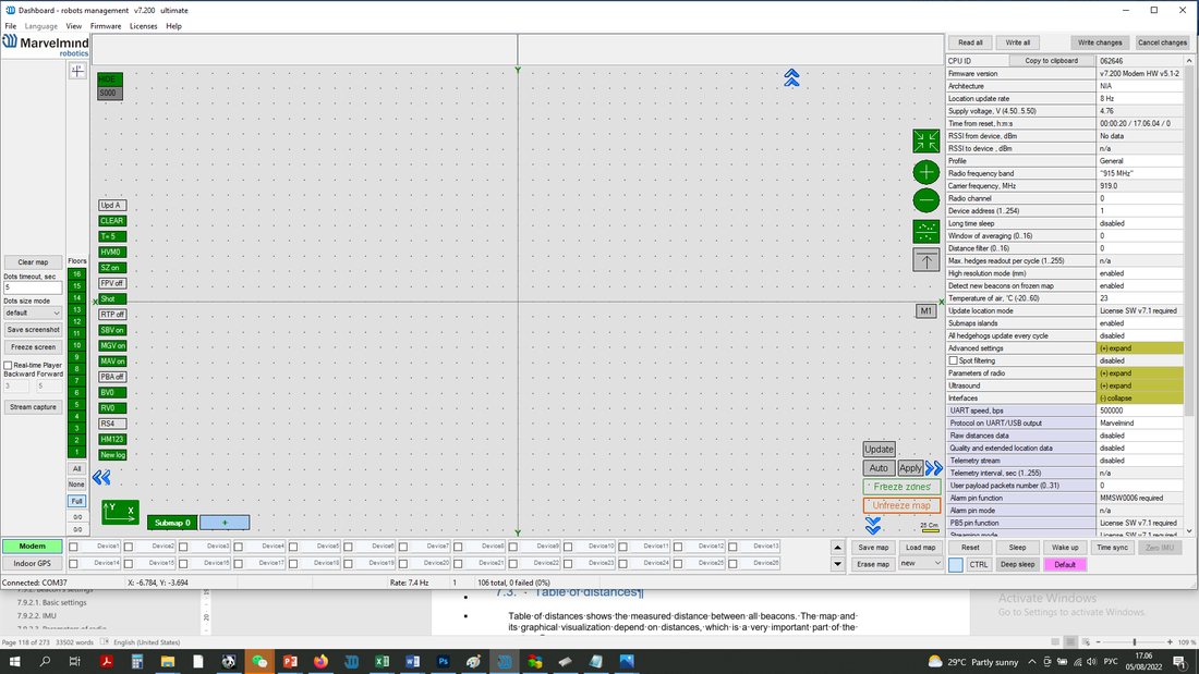
If the field is empty, the system found no issues with the launch. If you have any orange or red messages, please check them carefully and fix the problem.
There are 4 categories of reports:
- Orange – minor issue
- Red – major issue
- Green – Successfully completed settings
- Blue – Successfully completed process
Here is the list of the messages (relevant for Dashboard v7.200):
Left diagnostic window:
- Same ultrasonic frequency in submap0 beacons: n2, n3 – use beacons with different frequencies in IA submaps
- Paired beacons 25/26 ultrasonic and IMU fusion not completed. Angular difference: 45 degrees appears if the angle difference between beacons is more than 5 degrees
- IA architecture can’t be selected. Upload IA firmware to modem
- NIA architecture can’t be selected. Upload NIA firmware to modem
- MF NIA architecture can’t be selected. Upload NIA firmware to modem
- No MF NIA license (MMSW0004) for beacons n5, n6, n7. Buy the license. MF NIA doesn’t work even if the license is not activated for one beacon in the system
- Device N10 (V7.000) not supported
- N10 (V7.000) – too old. Update firmware
- N10 (V7.000) – newer than the dashboard. Update dashboard
- N10 (V7.000) – older than modem. Update firmware
- N10 (V7.000) – newer than modem. Update modem firmware
- Mixed IA and NIA devices
- UBX protocol for PX4 requires license MMSW0003. Buy the license
- Beacons not assigned to submaps: n10, n11. All submaps frozen. Unfreeze or add a submap
- Beacons not assigned to submaps: n10, n11. Maximum 4 beacons per submap. Add submap
- Beacons too close: n10, n11. Place beacons at least 2 meters from the modem
- Devices with duplicated addresses: n10, n11
- FEC mismatch to modem: n10, n11 – change FEC in radio parameters
- Discharged devices: n10, n11
- ‘Distances were changed in frozen submap0
- Sleeping beacons in frozen submap0
- Network setting read failed – Error reading Super-Modem network settings
- Network setting write failed – Error writing Super-Modem network settings
- Not found UWB device – connect UWB beacon or UWB modem to Modem HW v5.1 (only for Marvelmind UWB devices. In progress)
- Single hedge readout per cycle – increase the value and refreeze the map – In IA, the number of transmitted coordinates of hedgehogs per cycle 1 is entered in the modem settings. This greatly slows down the update of the coordinates of hedgehogs in the dashboard (if there are many of them). By default, this parameter is 10
- Modem HW v4.9 doesn”t support MF NIA
- You need at least 3 beacons for MF NIA. Add beacons
- Uploading map to beacons n10, n11, n12
- Check the table of distances for submap 0 – The table of distances is not white (there are discrepancies in distances)
- More than one beacon nailed to floorplan: n10, n11. Unnail for scaling
- Floorplan scaling: click the first point on the floorplan. ESC to cancel
- Floorplan scaling: click the second point on the floorplan. ESC to cancel
- Floorplan is glued. Can’t scale
- Floorplan is glued. Can’t move
- Can’t move submap – beacons n10, n11 are nailed to floorplan
- Can’t move submap – beacons n10, n11 are fixed
- Can’t rotate submap – beacons n10, n11 are nailed to floorplan
- Can’t rotate submap – beacons n10, n11 are fixed
- Can’t move: beacon n10 is nailed to floorplan
- More than one fixed beacon in submap0. Submap doesn’t automatically rebuild
- Not found USB connection. Possibly, the driver was not installed. Download and install driver
- Can’t set manual location. Beacon 10 is in frozen submap0. Unfreeze for manual location
- Enable Interfaces/IMU via modem/Raw IMU data to see gyro
- Enable Interfaces/IMU via modem/Raw IMU data to see the accelerometer
- Beacon n10 has no license MMSW0007. Buy the license
- Beacon n10 has no license MMSW0008. Buy the license
- Map upload finished
- Switch to recorded state 719 – Revert to the previous state by CTRL+Z (license 7.1 required)
- Licenses updated
- Paired beacons 25/26 ultrasonic and IMU fusion completed. Angular difference: 2 degrees. 4
- Network setting read completed
- Network setting write completed
Right diagnostic window:
- Adding beacons on frozen map disabled
- Stream capture mode was disabled
- Map is not frozen
- Submaps not frozen: 0, 1, 2
- No optional SW pack license (MMSW0005) for beacons: n10, n11
- Stream capture mode enabled
Table of Distances
The table of distances shows the measured distance between all beacons. The map and its graphical visualization depend on distances, an essential system part.
There are two ways of measuring:
- Measuring by ultrasound (automatic)
- Measuring by user (manual)
Measuring by ultrasound is impossible for Mini-RX and Industrial-RX beacons.
It is better to use manual input in noisy cases and cases with long distances.
Measuring by ultrasound:
In most cases, the system automatically builds the table of distances. If everything is good, there would be figures in cells, and they would change a little; the color of each cell would be white
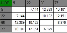
- If color differs, check the colors’ definitions (next page) and solve the problem
- Freeze the map only if the cells are white
Measuring by the user (necessary for Mini-RX beacons and Industrial-RX beacons and noisy cases):
- Use manual input if the table of distances wasn’t built. It may happen if the environment is boisterous, or the distances exceed the maximum possible range of the beacons. In that case, the cells’ color would be green
- Be careful with figures because a small mistake in the values will cause errors in location!
 For accurate distance measurements, see the Automatic submap self-calibration license
How to freeze/enter distance manually:
Open the Dashboard. You will see the table of distances
Right click on the cell you want to freeze/enter. An additional menu will open. There you can control the distances table. Choose Freeze distance for the pair to freeze it
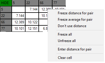
Now, cells are frozen. Those values would not change until you unfreeze them. Even if beacons had been moved, distance would stay. Be careful with frozen cells because a small mistake can significantly impact your tracking!
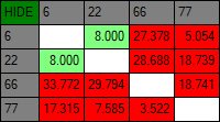
Repeat for all cells
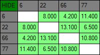
- White means that everything is good, you can freeze the map
- Green means frozen distance, you can freeze the map, but be careful with values
- Yellow means that something seems to be wrong, check distances and sensors before freezing
- Red means some critical misses, DO NOT freeze the map. Manually measure and enter distances
Multiple Devices Connected via USB
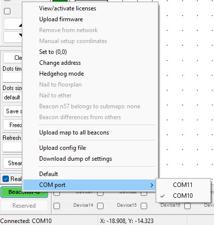
You can connect multiple devices to the Dashboard via USB and choose which you want to operate by choosing a different COM Port in the Dashboard.
To do that, just Right Mouse Button click on the device in the bottom left corner and choose a specific COM Port you want to use, or Right Mouse Button on the COM Port in the bottom left corner:
Figure 2. Choosing COM Port by clicking on COM Port status window
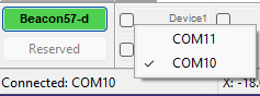
Figure 1. Choosing COM Port by clicking on Device button
Devices List
 The Devices list contains information about all the beacons in the system and allows users to search for, add, and delete beacons.
Modem automatically wakes up beacons which are turned on.
Devices in this section are divided into two types:
- Stationary beacon (beacon)
- Mobile beacon (hedge)
The devices list allows users to manage devices
Use double click to put the beacon into sleep mode
Stationary beacon (beacon)
Right click to open an additional menu
There you can:
Remove the beacon from the current submap
Remove the beacon from the whole network
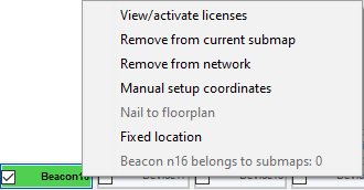
 Manually setup coordinates (x, y, z)
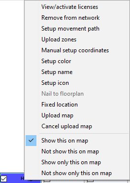 Mobile beacon (hedge)
- Right click to open an additional menu
There you can:
Remove the beacon from the network
Setup movement path
Upload zones (allowed and denied)
 Manually setup coordinates (x, y, z)
Visualization Settings
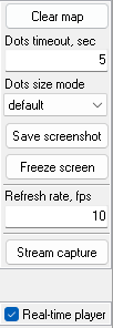
The visualization settings window has some functions to control the visualization process:
- Clear map – clear all movement path
 Dots timeout – time of path’s existence (Video: Help: Dots timeout)
- Dots size mode – the size of dots
- Save screenshot – screenshot file save to Dashboard’s folder/screenshots
 Freeze screen – The map freezes, no updates of the path
 Map Settings
 Dots timeout – time of path’s existence (Video:
  Freeze screen – The map freezes, no updates of the path
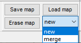
 Map Settings offer some helpful tools:
- Save map – saves map as .ini file into Dashboard folder/maps
- Load map – loads map from .ini format file
- Erase map – erases map and clears it
 New/merge – build a new map or upgrade the current map
Dashboard Monitoring Mode
 New/merge – build a new map or upgrade the current map
Dashboard Monitoring Mode is a mode that allows you to observe tracking without any ability to control and modify the system.
Now, you can divide permissions between users to avoid accidental changes to any settings and the system being corrupted. That is something like a safety button.
This is the first version of Dashboard Monitoring Mode. New functionality and appearance may come with future SW updates
How to enable Dashboard Monitoring Mode:
 Click on the “Stream capture” button (It will be renamed in future updates into “Dashboard Monitoring Mode”)
 Click on the “Stream capture” button (It will be renamed in future updates into “Dashboard Monitoring Mode”)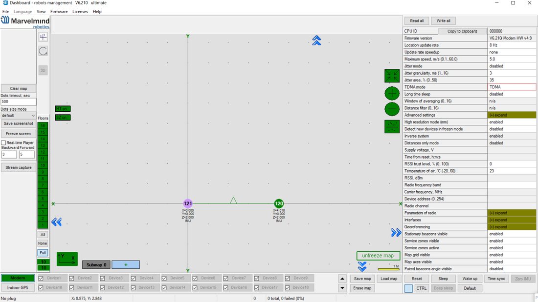
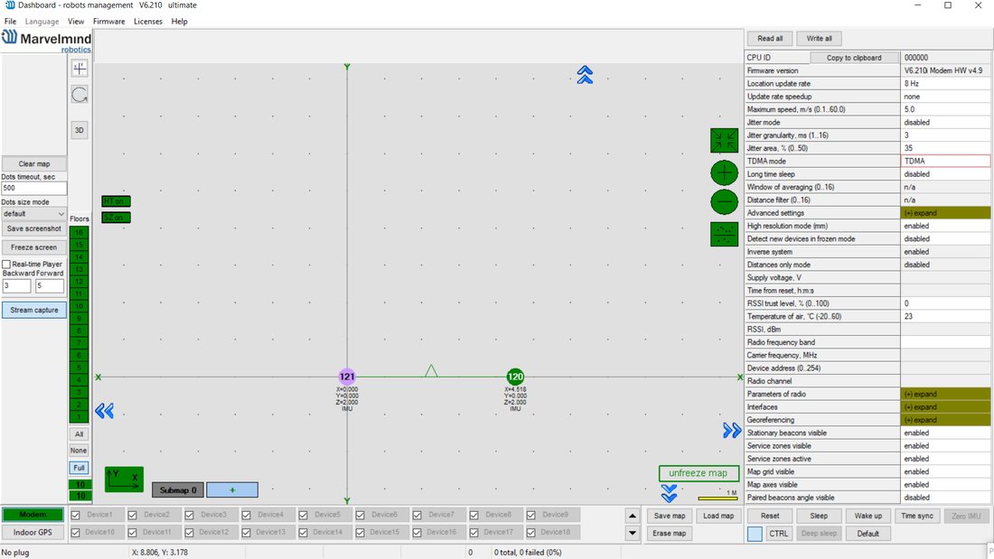
- If user changes any settings, ‘dashboard monitoring mode’ automatically disables and corresponding message is shown in top right information field.
Modem/Beacon’s Quick Control Panel
The control panel allows the user to interact with devices. It can work with one device or with all devices in the system.
List of functions:
- Reset – Resets device
- Sleep – Send device asleep (battery economy mode)
- Wake up – Wakes up the device (from sleeping mode)
- Default – Drops all device’s settings to factory default
 Time sync – Sends time from your PC to Hedgehog (for stream it out via UART)
 Time sync – Sends time from your PC to Hedgehog (for stream it out via UART)
Additional Ctrl feature:
- To apply the action to all beacons in the system, use Ctrl + Left Click on the button. This applies only to buttons that turn bold while Ctrl is pressed.

- The CTRL button can replace the physical keyboard button for devices without a keyboard.

Celling and Mirroring Buttons on the Dashboard
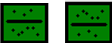
 The Mirroring button allows the map to be displayed as a mirror reflection
- The Ceiling button shows where the mobile beacon is located with respect to the stationary beacons
- When the arrow points up, it means that the mobile beacon is below the stationary beacon
- When the arrow points down, it means that the mobile beacon is above the stationary beacons
 The Center Map button
Detailed Settings
 The Mirroring button allows the map to be displayed as a mirror reflection
 When the arrow points up, it means that the mobile beacon is below the stationary beacon
 When the arrow points down, it means that the mobile beacon is above the stationary beacons
 The Center Map button
This bar allows users to adjust devices very precisely. It contains a lot of parameters for advanced usage
Modem Settings Basic Settings
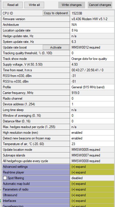
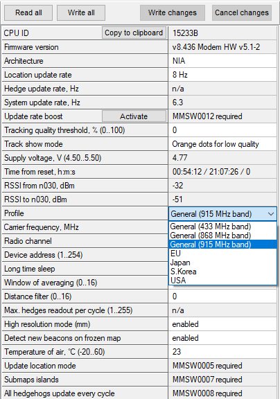
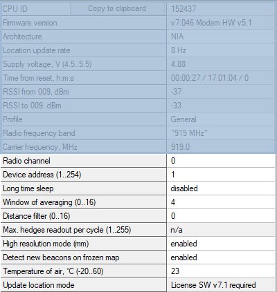
Unique processor ID for each device (beacon or modem)
Firmware version of device (beacon or modem)
Architecture type (IA or NIA)
Location update rate settings: 1/20 Hz – 16 Hz+.
Notice that real update rate may be limited by distances between beacons or radio profile
Power supply voltage of the device 5 V+-0.2 V is OK
Strength of the radio signal from modem to beacons and vice versa. Maintain in the range of -25 dBm to -80..-90 dBm. Higher value – may overload. Lower – lost packets
Strength of the radio signal to modem from beacons and vice versa. Maintain in the range of -25 dBm to -80..-90 dBm. Higher value – may overload. Lower – lost packets
Time from the latest reset
Chosen working band
Exact working frequency
TBD
Measured temperature of the processor’s crystal
If map is frozen, new beacons will be accepted in the map, if enabled
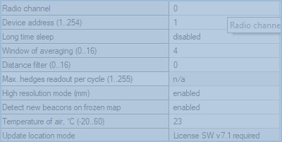
Keep Enabled normally. Switch to cm for backward compatibility
TBD
Filter of distances (as opposed to filter of locations). More – better filtering, but may be too conservative and “kill” good measurements
Averaging between location update measurements. More value – less location jitter, but higher latency
TBD
Logical address of the device. Keep 2..255 for beacons.
Address
Pre-selected channel – one of the radio channels for communication between modem and beacons
Advanced Settings
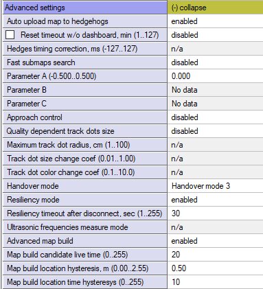
- TBD
- TBD
- TBD
- TBD
- TBD
- TBD
- TBD
- TBD
- TBD
If modem lost connection it restarts by itself
TBD
Parameters of Radio
Real carrier frequency
Selected radio profile with a set of profile settings.
Choose between 38 kbps (better range and interference immunity, but slower); 153 kbps – balanced; and 500 kbps – the fastest, but the lowest radio range and least immune to interference
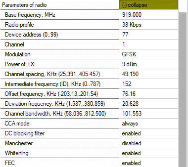
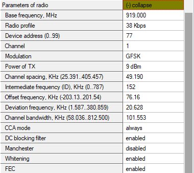
Only for advanced users
Only for advanced users
Only for advanced users
Modulation – a part of the radio profile. Only for advanced users
One of a predefined radio frequency channels
Logical address of the device. Distinguish of beacon from another
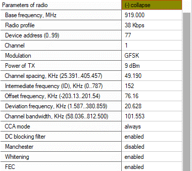
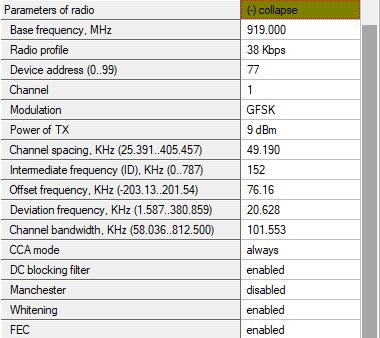
Radio profile settings. No need to change manually. Only for advanced users
Radio profile settings. No need to change manually. Only for advanced users
Radio profile settings. No need to change manually. Only for advanced users
Radio profile settings. No need to change manually. Only for advanced users
Radio profile settings. No need to change manually. Only for advanced users
Radio profile settings. No need to change manually. Only for advanced users
Radio profile settings. No need to change manually. Only for advanced users
Radio profile settings. No need to change manually. Only for advanced users
Interfaces
Enable or disable receiving raw IMU data with IMU update rate (100 Hz)
- Type of protocol
- Speed of UART
- TBD
- TBD
- TBD
- TBD
- TBD
- TBD
- TBD
- TBD
Beacon’s Settings Basic Settings
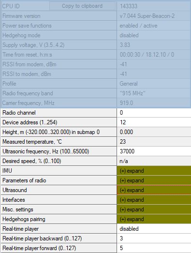
Unique CPU ID
Firmware version of device (beacon or modem)
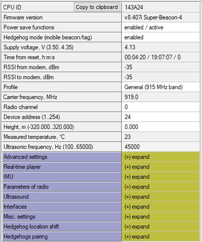
Measured voltage of internal battery
Enable for mobile beacon and disable for stationary beacon
TBD
Time from the latest reset
Strength of the radio signal from modem to this beacon, i.e. how the beacon “hears” the modem over radio. Keep below -25 dBm and above -80 dBm to avoid losses of packets. Lower end depends on radio profile and interference
Strength of the radio signal from this beacon to the modem, i.e. how the modem “hears” the beacon over radio. Keep below -25 dBm and above -80 dBm to avoid losses of packets. Lower end depends on radio profile and interference
Select radio frequency band according to your HW: 433 MHz or 915 MHz
Real carrier frequency
TBD
TBD
TBD
Selected radio channel
Selected device’s address
Height – must be set for stationary beacons.
Must also be set for mobile beacons in 1D or 2D modes
Processor’s crystal’s temperature
Frequency of ultrasonic pulses – set according to your HW
TBD

IMU
Calibration settings of embedded IMU: X shift
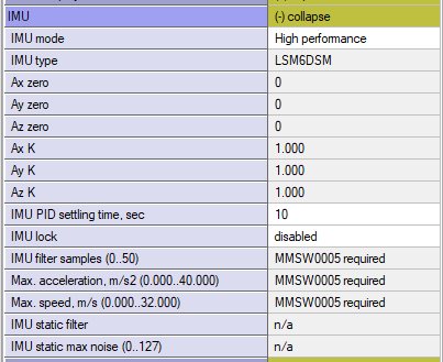
Calibration settings of embedded IMU: Y shift
Calibration settings of embedded IMU: Z shift
Calibration settings of embedded IMU: X scale
Calibration settings of embedded IMU: Z scale
Calibration settings of embedded IMU: Y scale
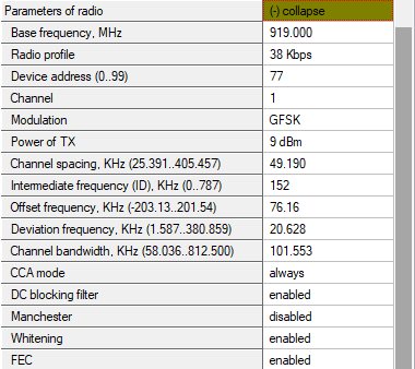
Parameters of Radio
Real carrier frequency
Radio profile that is linked with many radio settings below. Helps to set them at once by choosing the profile. See similar in modem for more info
Device address – shall be set for each beacon different under one modem
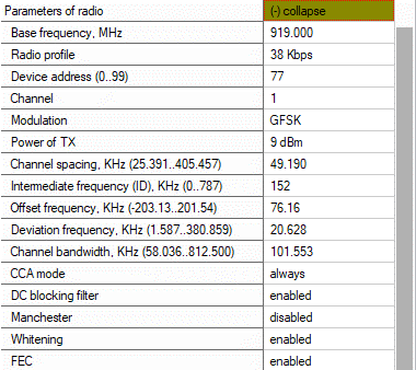
One of the pre-selected frequency channels
Radio profile settings. No need to change manually. Only for advanced users
Radio profile settings. No need to change manually. Only for advanced users
Radio profile settings. No need to change manually. Only for advanced users
Radio profile settings. No need to change manually. Only for advanced users
Radio profile settings. No need to change manually. Only for advanced users
Radio profile settings. No need to change manually. Only for advanced users
Radio profile settings. No need to change manually. Only for advanced users
Radio profile settings. No need to change manually. Only for advanced users
Radio profile settings. No need to change manually. Only for advanced users
Radio profile settings. No need to change manually. Only for advanced users
Radio profile settings. No need to change manually. Only for advanced users
Radio profile settings. No need to change manually. Only for advanced users
Ultrasound
TX-RX – regular mode. Use it. The rest – internal
TBD
Power saving features. If not sure, keep default
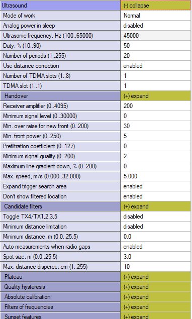

Automatic or manual gain control.
Manual can be useful in special conditions: too high external audio noise, for example
Number of ultrasonic pulses the TX beacon emits. More – stronger, but longer echo. For small distances – 1-10 periods. 20-30 – for 10-20 meters. For 20+ m – 50 periods
Internal settings
50% – default. 1% … 99% lower strength of ultrasonic.
Keep default
TBD
Power saving features. If not sure, keep default
Frequency of ultrasonic pulses – set according to your HW
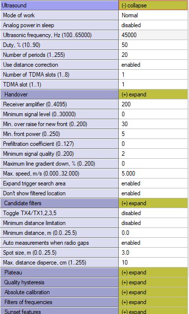

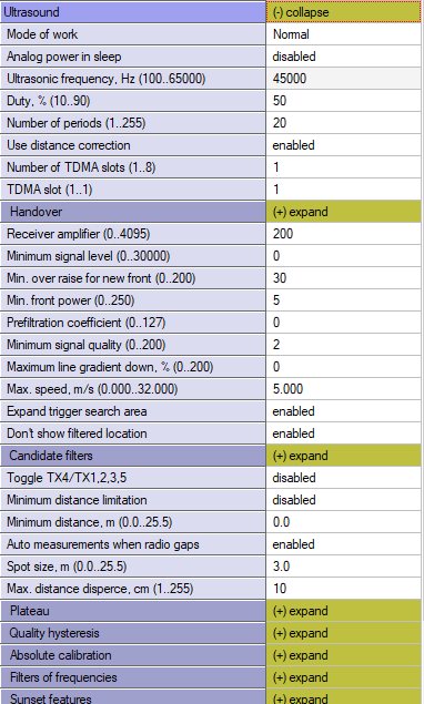

TBD
AGC settings. For advanced users only
AGC settings. For advanced users only
AGC settings. For advanced users only
AGC settings. For advanced users only
Deep ultrasonic trigger settings. For special cases only
Deep ultrasonic trigger settings. For special cases only
Keep ADC
Deep ultrasonic trigger settings. For special cases only
Deep ultrasonic trigger settings. For special cases only
Deep ultrasonic trigger settings. For special cases only
Deep ultrasonic trigger settings. For special cases only
Deep ultrasonic trigger settings. For special cases only
Deep ultrasonic trigger settings. For special cases only
Deep ultrasonic trigger settings. For special cases only
Deep AGC settings. For special cases only
Deep AGC settings. For special cases only
Deep AGC settings. For special cases only
Deep AGC settings. For special cases only
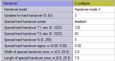
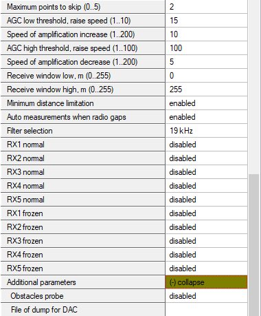
Enable/disable sensor RX2 in map building mode
Enable/disable sensor RX1 in map building mode
- TBD
- TBD
- TBD
- TBD
- TBD
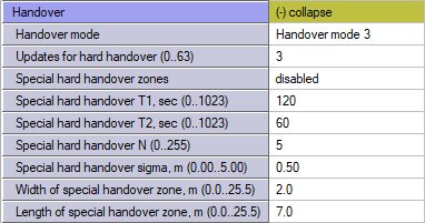
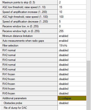
TBD
Enable/disable sensor RX5 in map frozen/regular work mode
Enable/disable sensor RX4 in map frozen/regular work mode
Enable/disable sensor RX2 in map frozen/regular work mode
Enable/disable sensor RX3 in map frozen/regular work mode
Enable/disable sensor RX1 in map frozen/regular work mode
Enable/disable sensor RX4 in map building mode
Enable/disable sensor RX3 in map building mode
Enable/disable sensor RX5 in map building mode
TBD
TBD
Interfaces
Speed of UART in hedgehog mode
Type of protocol
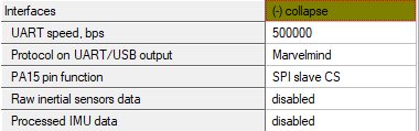
Enable or disable receiving raw IMU data with IMU update rate (100 Hz)
TBD
Enable or disable receiving IMU+ultrasonic sensor fusion data with IMU update rate (100 Hz)
Georeferencing
The same as with modem

The same as with modem
Misc. Settings

Timeout sleep settings
Hedgehogs Pairing Settings
Enable for Paired Beacons feature
Check chapter Paired Beacons for more details
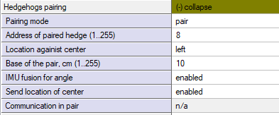
In IA: via UART, via Radio
In NIA: Not applicable
If disabled, location of the beacon will be sent
If disabled, data will be sent only based on ultrasound
Actual distance between paired hedgehogs
Location against center of selected beacon in a pair
Address of the beacon, current selected hedgehog paired with
Activate this parameter to pair beacons
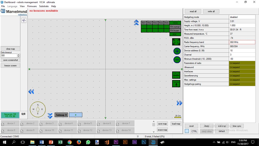
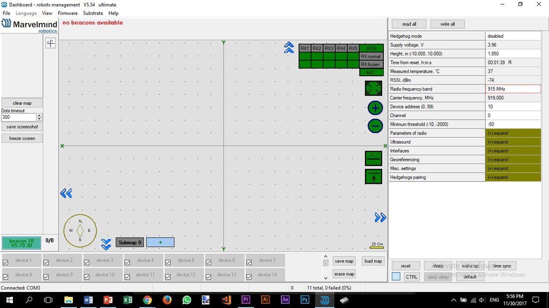
Radio Frequency Band and Carrier Frequency
*Mini-RX beacons and Super-Beacons are 868/915 MHz only
It is possible to change the radio frequency, but radio performance can be severely degraded. It may be enough for smaller distances, up to 10-20 meters, but not more.
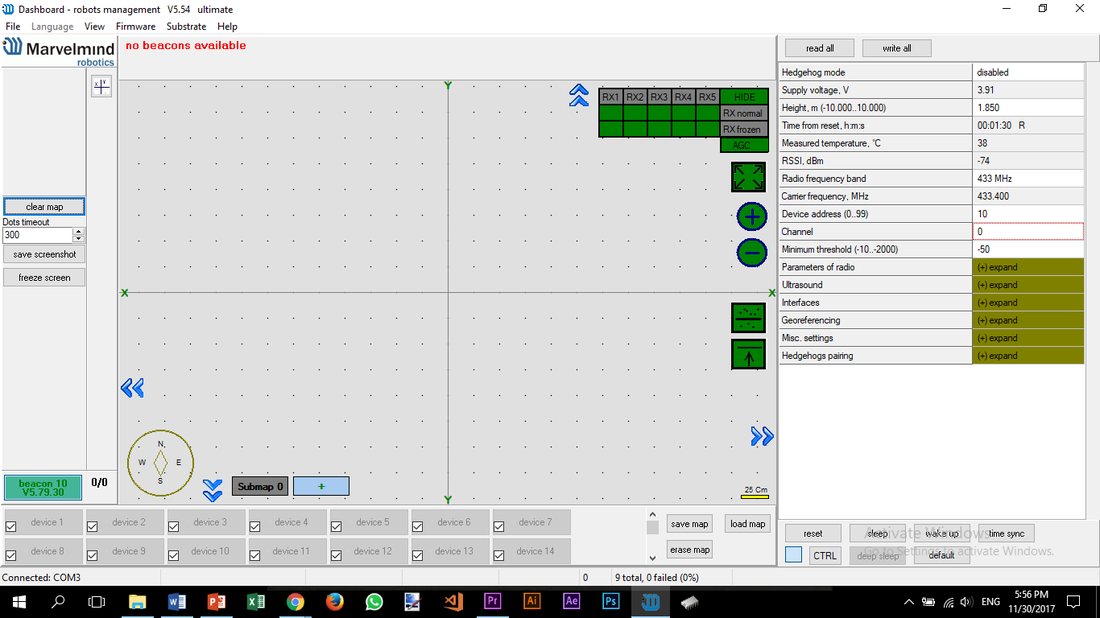
Different Beacons’ Designations in the Dashboard
You can choose any color for your hedge, but it still has some permanent colors, which inform you about some tracking issues:
- Blue – standard mode and confident tracking
- Orange – system provides the best location data possible, but confidence is lower than blue
- Transparent Blue – lost radio packets
- Transparent Orange – weak ultrasonic coverage
- Blinking Yellow – no data from a beacon
- Red – beacon is outside of the geofencing zone
- Blinking Grey – no connection to a beacon
Different Beacons’ Colors in the Dashboard
Beacons can have different ultrasonic frequencies. Because of that, they have other colors to make them easier to distinguish:
- Stationary beacons – Green center –
- Mobile beacons – Dark blue center –
- Different colors of stationary beacons are only in the IA architecture. In NIA, the stationary beacons are all green. Vice versa for IA, mobile beacons are all blue.
Examples:
- Stationary beacons:
- 19 KHz
- 22 kHz
- 25 KHz
- 28 kHz
- 31 KHz
- 34 kHz
- 37 KHz
- 45 KHz
- Mobile beacons:
- 19 KHz
- 22 kHz
- 25 KHz
- 28 kHz
- 31 KHz
- 34 kHz
- 37 KHz
- 45 KHz