
Software settings
This chapter as a clean, readable HTML page.
The “Software settings” chapter of the Operating Manual, reproduced as a real HTML page. Anything unclear? Open the original PDF of just this chapter (pages 83-98) (also pinned top-left). Hub: all chapters.
Super-Modem’s SW Update and Configuration Description Super-Modem’s SW Update
 Do not disassemble the Super-Modem before you check the SW version installed. First, check if the SW version of your Super-Modem is up to date (the latest version is on the Marvelmind Downloads page). If not, update the software as described below
Marvelmind Super-Modem software consists of two parts:
- Low-level firmware
- High-level software for integrated Raspberry Pi single-board computer
Low-level firmware is included in the general software package with all Marvelmind software in the ‘Super-Modem’ folder. Like other firmware in the package, this firmware can be updated via Dashboard (hex file) or via DFU (pdf file). See the SW Update (USB/Radio/DFU) chapter of this manual for details on updating software via Dashboard or DFU.
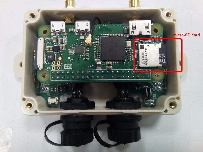
High-level software is located on a microSD card inserted in the Raspberry Pi single-board computer inside a Super-Modem. To update this software, you should write the image of the microSD card with updated software on it. You can download the image on the Downloads page. The image is placed in an archive separately from the general software package because it is large (about 1.5 – 2 GB).
Micro-SD card location
How to Update Super-Modem (for SW Version from v7.000)
In the latest versions of SW, it’s possible to flash Super-Modem without dissembling.
Connect the power supply to the Super-Modem and connect the Super-Modem to the PC via USB. Wait for 1 minute till it appears in Dashboard
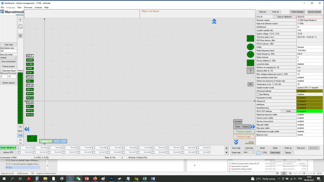
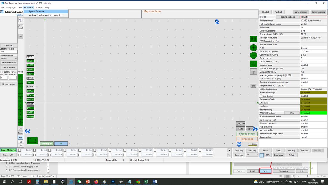 There are two Firmware versions: low-level (Firmware version) and high-level (high-level software version). Both should be flashed from the same pack.
Go to Firmware => Upload firmware
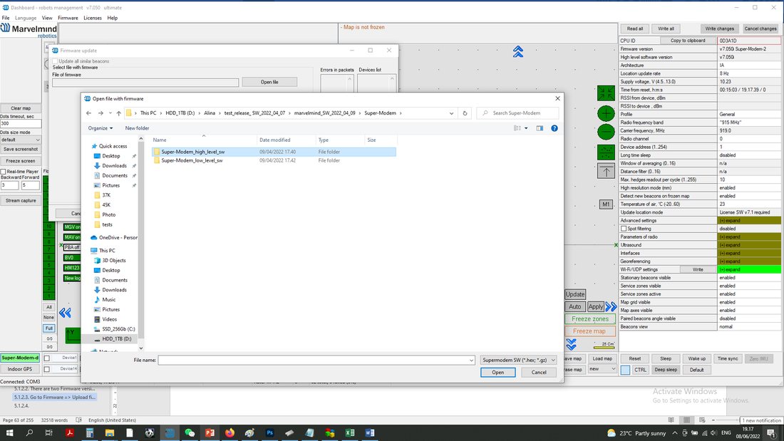 Update high-level SW (from folder Super-Modem_high_level SW)
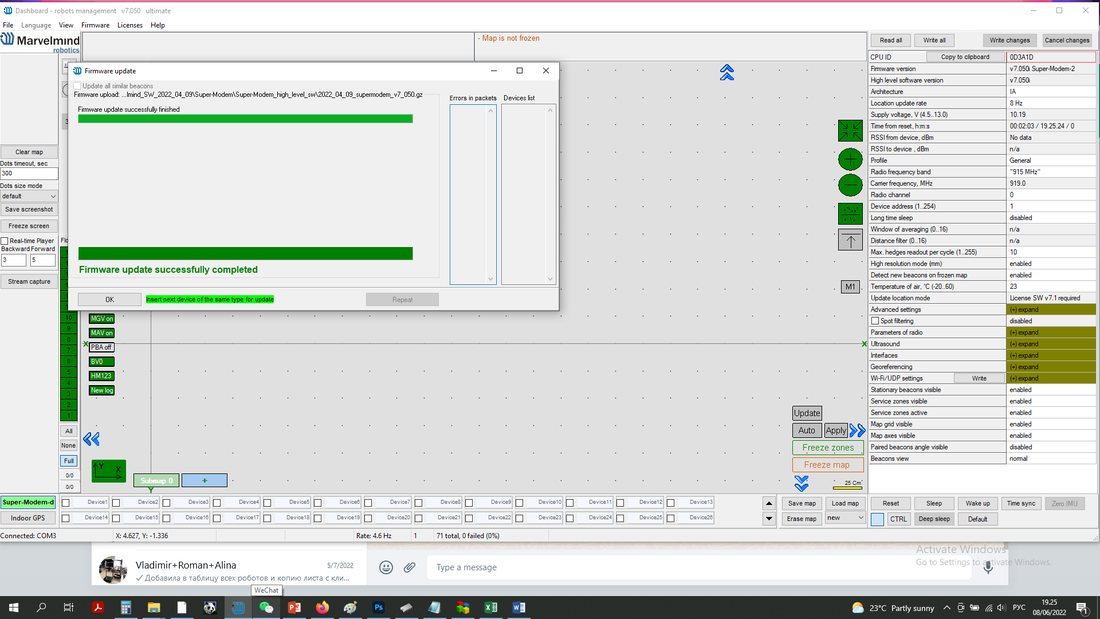 When high-level flashing is done, use the file from folder Super-Modem_low_level_SW
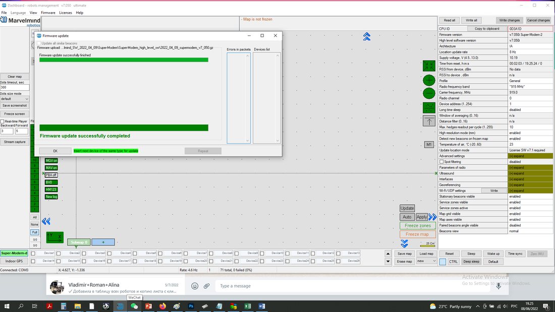
Press the Default button after flashing both levels.
Firmware update completed.
How to Update Super-Modem’s SW (for SW Version Older than v7.000):
 Do not disassemble the Super-Modem before you check the SW version installed. First, check if the SW version of your Super-Modem is up to date (The latest version is on the Downloads page). If not – update the software as described below
Follow the steps below to update Super-Modem’s SW.
Open Super-Modem enclosure
Eject the micro-SD card (Super-Modem should not be powered at this time)
Insert micro-SD card into any MS Windows computer via card reader
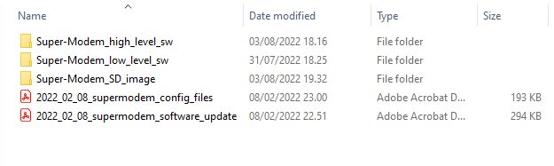 Download and unpack the archive with the image of updated software
Install and run the Win32 disk imager program (supplied in the archive with the image)
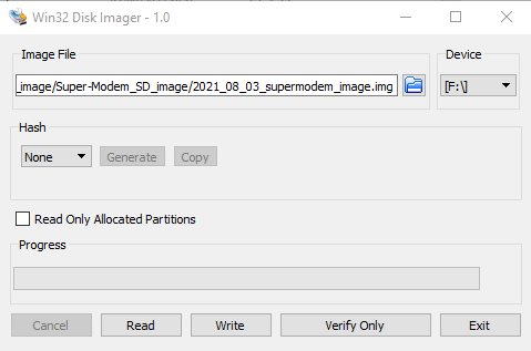 Open the image file and write to the micro-SD card (see screenshot below)
Eject the micro-SD card from the computer and insert it back into Super-Modem
Close Super-Modem enclosure
Super-Modem’s Configuration
Marvelmind Super-Modem contains a Raspberry Pi single-board computer with corresponding software. Settings can be modified via the configuration menu in the Dashboard.
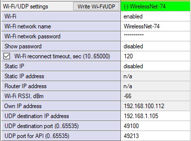
Name (SSID) of Wi-Fi network to connect
Password (PSK) for this network
IP address in local network where Super-Modem will stream data
UDP port where Super-Modem will stream data
 If you need more information about API streaming here.
SW Update (USB/Radio/DFU)
This chapter describes three general ways of updating SW: regular, using a USB or Radio connection, and SW update for special cases (if the SW version gap is very big or regular SW updates do not work): DFU Programming.
SW Update via USB
Usually, the SW update via USB is used the first time the system is started up. It allows you to update to the actual SW version very quickly before the system deployment.
Pros: Quick SW update per beacon.
Cons: All the devices should be connected to the PC via a USB cable. If you already deployed the system, you would need to unmount it.
How to:
- Launch the Dashboard
- Make sure that the beacon is on
- Connect the beacon to your PC via a USB cable
 When the beacon is connected to the Dashboard, go to “Firmware” → “Upload firmware”
- Choose a .hex SW file for your device (Be careful with IA and NIA architectures, do not mix them)
- Click “Next”
- Wait until the beacon update finishes
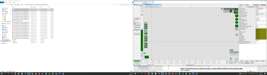 When the beacon is connected to the Dashboard, go to “Firmware” → “Upload firmware”
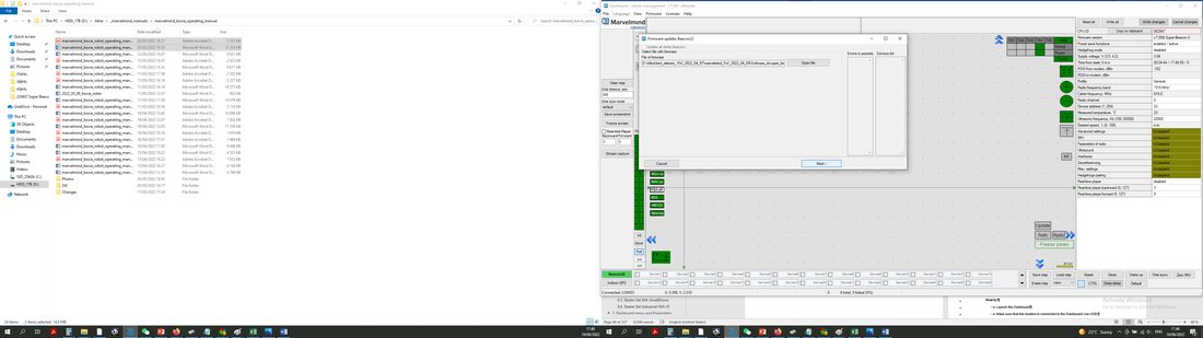 Choose a .hex SW file for your device (Be careful with IA and NIA architectures, do not mix them)
Note: Press the Default button for every beacon after the SW update
- Repeat for all your beacons
 Be careful: The default button will apply full default settings to this beacon, except its address. If you had some custom Radio settings before, it would be changed to the default Radio profile for your beacon hardware (200 kbps for new beacons; see Radio Profiles Compatibility for details), Radio channel 0.
SW Update via Radio
Usually, the SW update via USB is used the first time the system is started up. It allows you to update to the actual SW version very quickly before system deployment.
Pros: Allows you to keep your system in its place and update SW remotely
Cons: Not as fast as USB SW update
How to:
- Launch the Dashboard
- Make sure that the modem is connected to the Dashboard (via USB)
- Ensure that you can see your beacons via radio in the Dashboard
- Click on the beacon you want to update (In the bottom devices’ list)
- go to “Firmware” → “Upload firmware” → Choose the .hex SW file for your device (Be careful with IA and NIA architectures, do not mix them)
- Click “Next”
- Wait until the beacon update finishes
- Repeat for all your beacons
- Note: with license MMSW0005, you can enable simultaneous updates of multiple beacons (stationary and mobile)
SW Update via DFU Programming
Not applicable to “Outdoor” versions of initially non-outdoor versions (DFU re-flashing is not available for these products: they are sealed with compound and the DIP switch cannot be switched to DFU mode: Modem HW v5.1 Outdoor, Super-Beacon Outdoor, Mini-RX IP67)
Usually, SW updates happen using regular USB or Radio SW updates. But if you haven’t updated your system for a long time (and get a big SW version gap) or are faced with some unexpected troubles, please do the DFU Programming SW update. This chapter describes DFU updates for different types of devices.
Pros: The Ultimatum SW update erases all glitches, settings, etc. It allows the beacon to be revived if “everything goes bad.”
Cons: It is more complicated than a regular SW update and clears all settings. Save the map file to avoid losing your map.
To do DFU programming, you must know where the hardware reset button and DIP switches are placed.
Reset Button and DIP Switch Placement
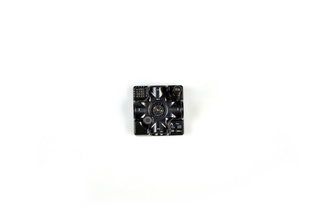
Reset button
DIP switches
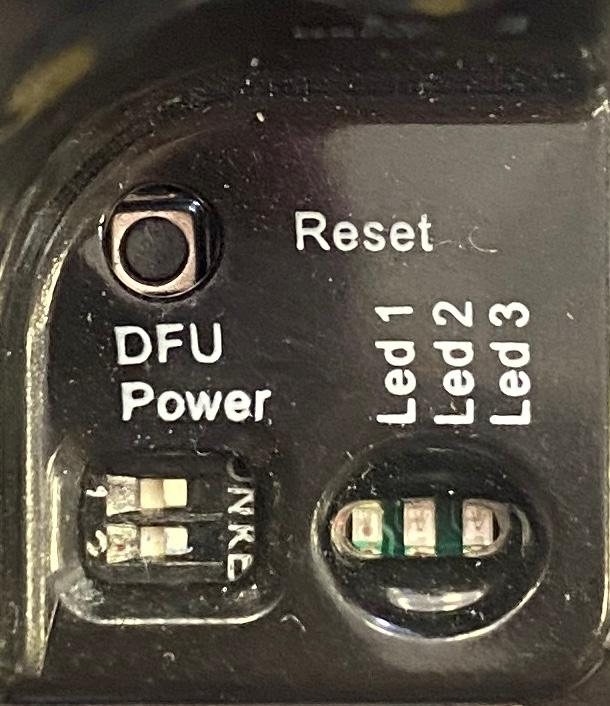

DIP switches
Reset button (on side)
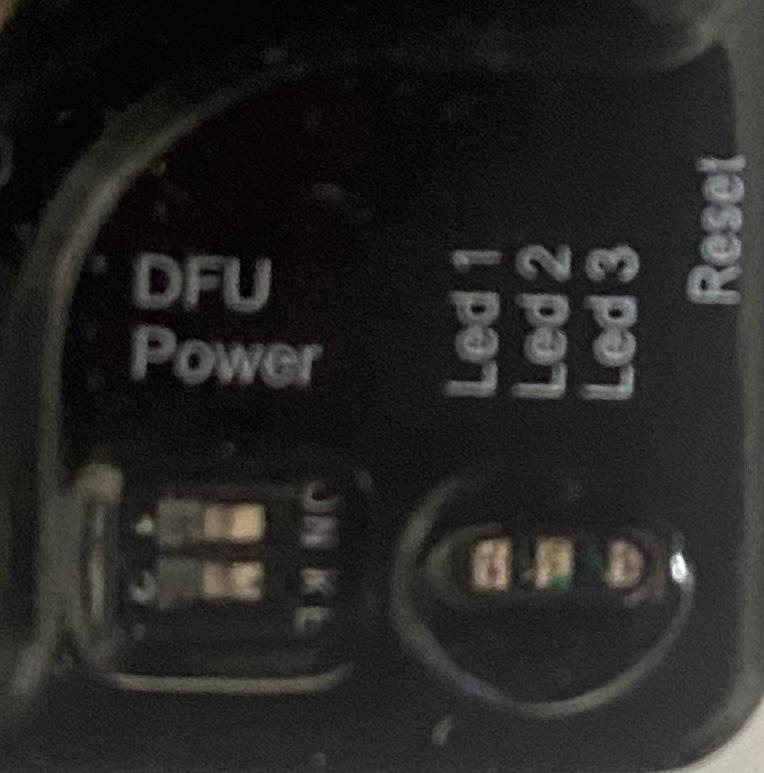
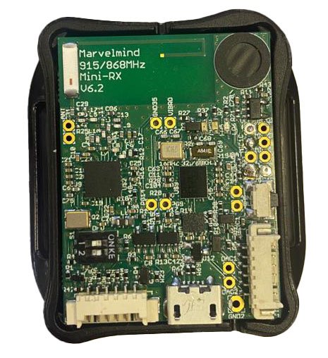
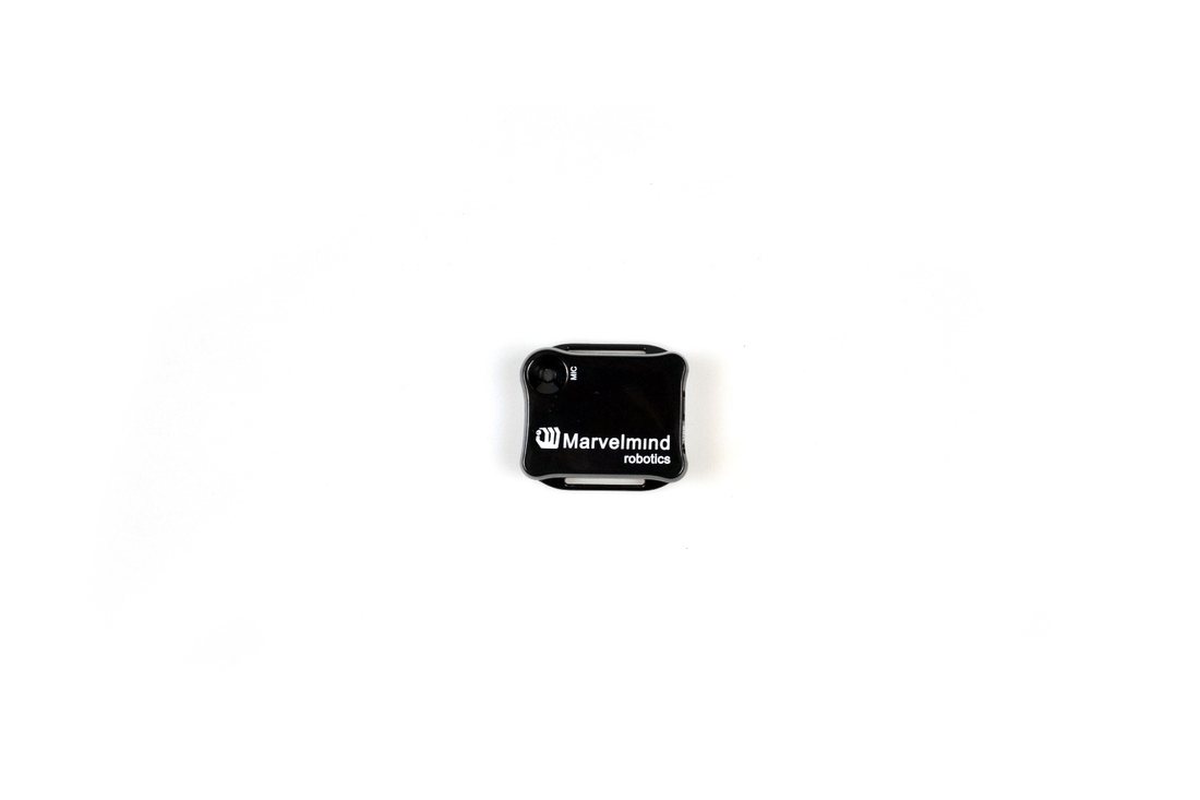
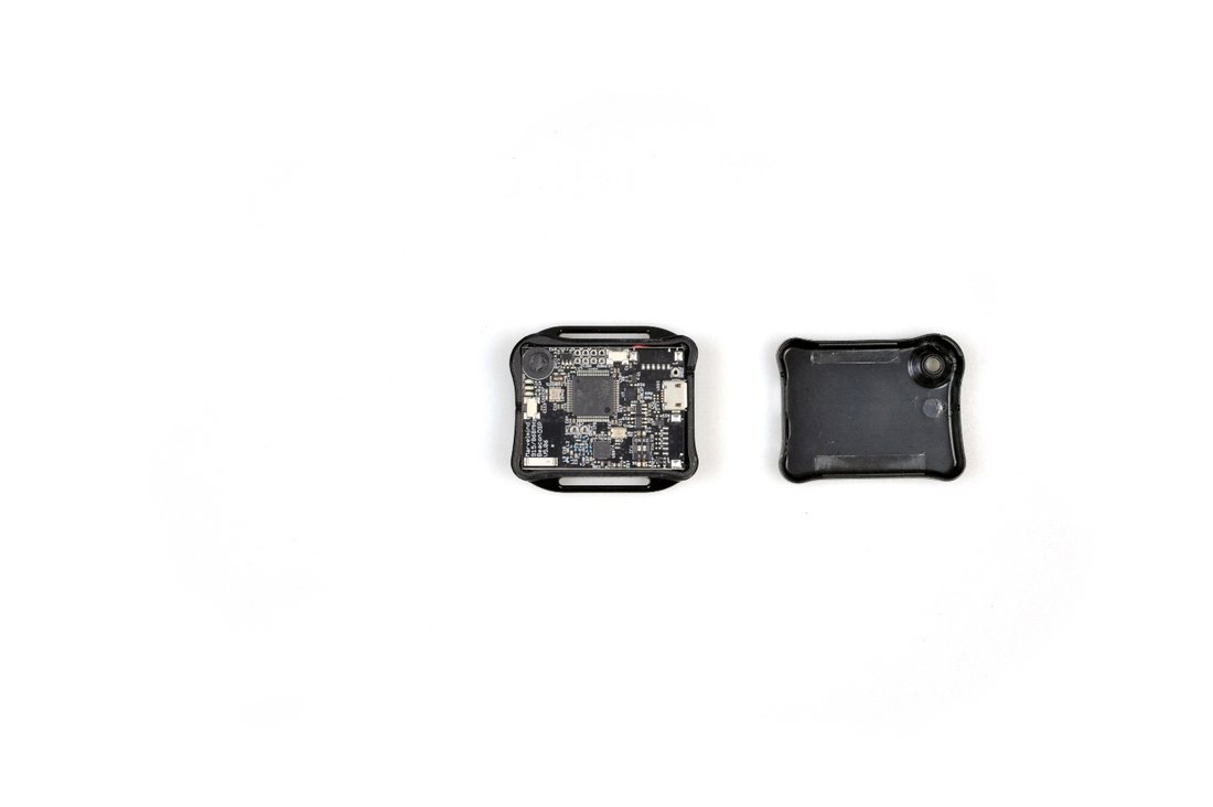
DIP switches
Disassemble
Carefully
Reset button
 Mini-TX beacon:
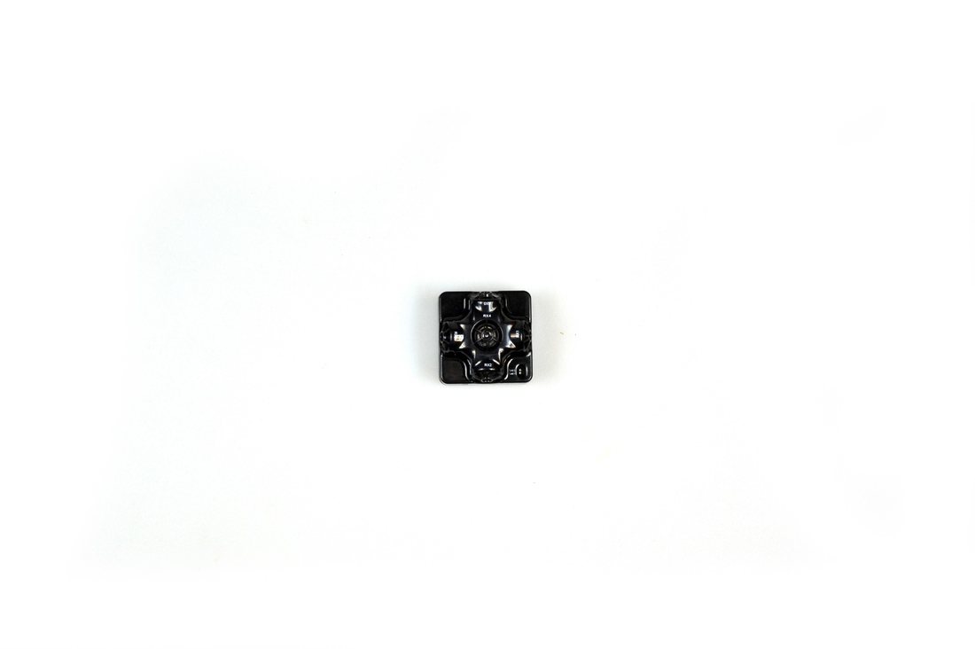
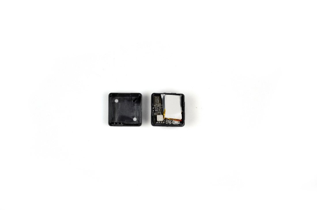
DIP switches
Reset button (on the other side)
Disassemble
Carefully
Industrial beacons have no switches and reset buttons, but they have magnetic DFU switches and magnetic Reset buttons:
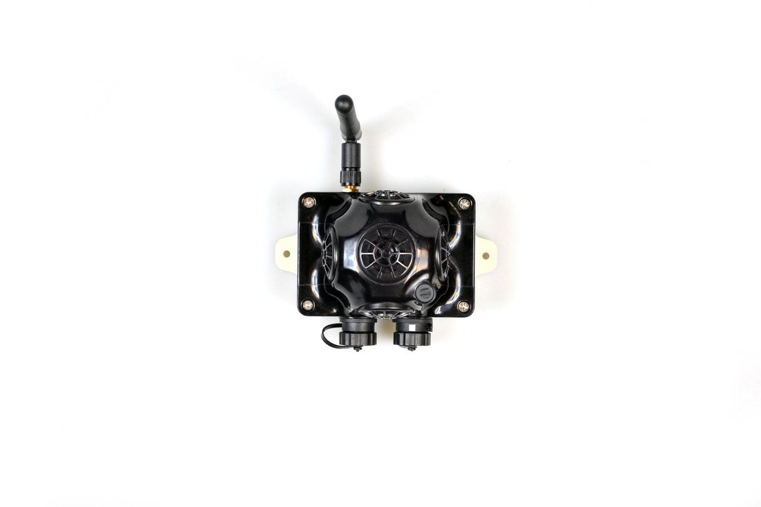
Magnetic DFU switch side
Magnetic Reset side
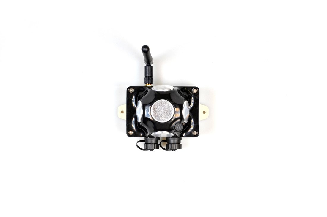
Magnetic DFU switch side
Magnetic Reset side
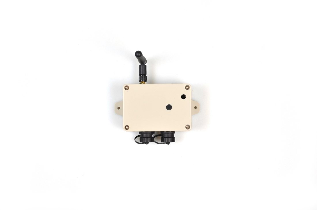
Magnetic DFU switch side
Magnetic Reset side
How to enter DFU mode and reset different types of Modems:
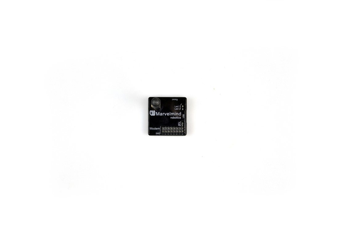
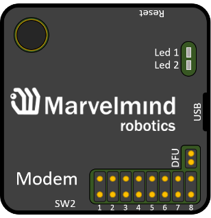
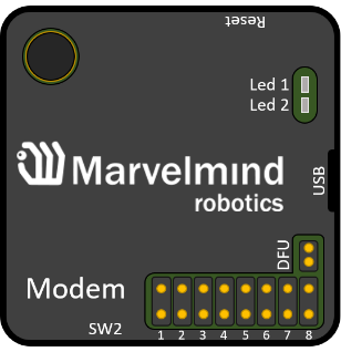
Hardware Reset button (on side)
DFU mode pins
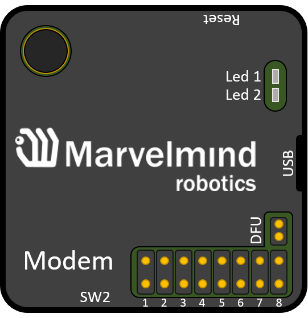
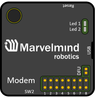
Hardware Reset button (on side)
DFU mode pins
Magnetic DFU switch side
Magnetic Reset side
For regular and non-industrial versions of beacons – switch DIP switches into positions shown on the picture (both up) and press the Reset button – the device will go into DFU mode
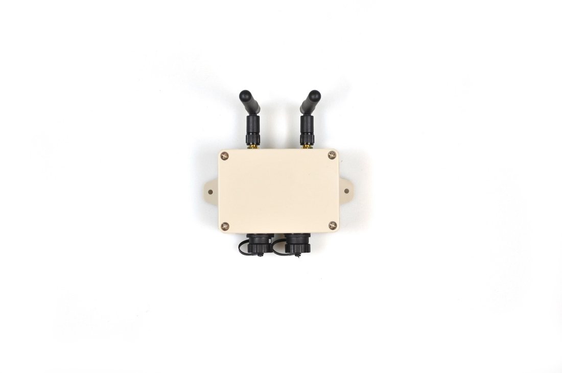
 For Industrial versions of beacon and Super-Modem – attach one magnet to the DFU switch side and attach for 1 second the second magnet to the Reset side of the device – the device will go into DFU mode (Do not forget to power Industrial versions of beacons and Super-Modem – they do not have an internal battery)
For Modem HW v5.1 – short DFU mode pins and press the Reset button – the device will go into DFU mode
Connect the device via USB to your PC (Remember to power the Industrial versions of beacons and Super-Modem-they do not have an internal battery)
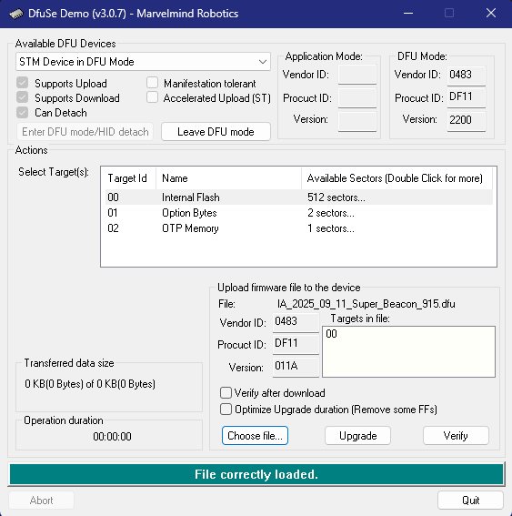
 Run DfuSe (Marvelmind DfuSe located in the software package)
- In the upper left corner of the DfuSe program, you will see a device connected in DFU mode (if not, reenter the device into DFU mode)
- Choose the DFU file for the beacon. Note: by default, the correct firmware file is automatically selected for your device’s current architecture (IA or NIA). Manual file selection is only required if you need to re-flash the device to a different architecture
- Click the UPGRADE button
- After a few seconds, the DFU will be uploaded to the beacon. Make sure it takes 1-3 seconds and does not happen instantly. Otherwise, the SW has not been uploaded correctly. If the DFU appears to upload immediately, check the "Choose" button you used or change the version of DfuSe SW you selected
Exit from the DFU mode:
For regular and non-industrial versions of beacons – switch DIP switches into positions shown on the picture (Left – down, right – up) and press the Reset button – the device will exit from DFU mode
For Industrial versions of beacon and Super-Modem – remove one from the DFU switch side and attach for 1 second the second magnet to the Reset side of the device – the device will exit from DFU mode
For Modem HW v5.1 – remove the circuit plug DFU mode pins and press the Reset button – the device will exit DFU mode
 Start the Dashboard. Leave the device connected to the PC via USB (Do not forget to power the Industrial versions of beacon and Super-Modem, they do not have an internal battery). The device should appear in the Dashboard
- Check SW on the beacon afterward
- Everything should be OK with SW now. DFU programming is complete
- DFU Troubleshooting
 Start the Dashboard. Leave the device connected to the PC via USB (Do not forget to power the Industrial versions of beacon and Super-Modem, they do not have an internal battery). The device should appear in the Dashboard
If you experience difficulties in DFU programming, please try the following:
Change the USB cable
Try different USB ports on your computer
Use a different computer with a different version of Windows or another operating system
For more information check DFU update troubleshooting manual
SW Update via Bootloader
If you face a situation where a certain device is not showing up in the Dashboard, you can try to update it via Bootloader. There can be several reasons why the device may not show up in the Dashboard, such as corrupted firmware or incorrect version of firmware for a certain device (for example uploading Mini-RX firmware to Super-Beacon).
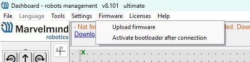
Figure 1. Activate Bootloader button
After checking this option follow the next steps:
- Connect your device
- It will appear as a Bootloader device
- Choose the preferred firmware in the next 10 seconds
- After update device will appear in normal mode
- Don’t forget to uncheck Activate bootloader after connection option
If the device hasn’t appeared in the Dashboard as a Bootloader press Reset button on the device according to this chapter. If the device hasn’t appeared in this case too it might indicate that bootloader firmware has been corrupted too. Stick to the updating device via DFU mode according to DFU programming chapter.