
Hardware: system elements
This chapter as a clean, readable HTML page.
The “Hardware: system elements” chapter of the Operating Manual, reproduced as a real HTML page. Anything unclear? Open the original PDF of just this chapter (pages 31-70) (also pinned top-left). Hub: all chapters.
Here are represented the core elements required for the stable working of the system:
Control System (Dashboard)
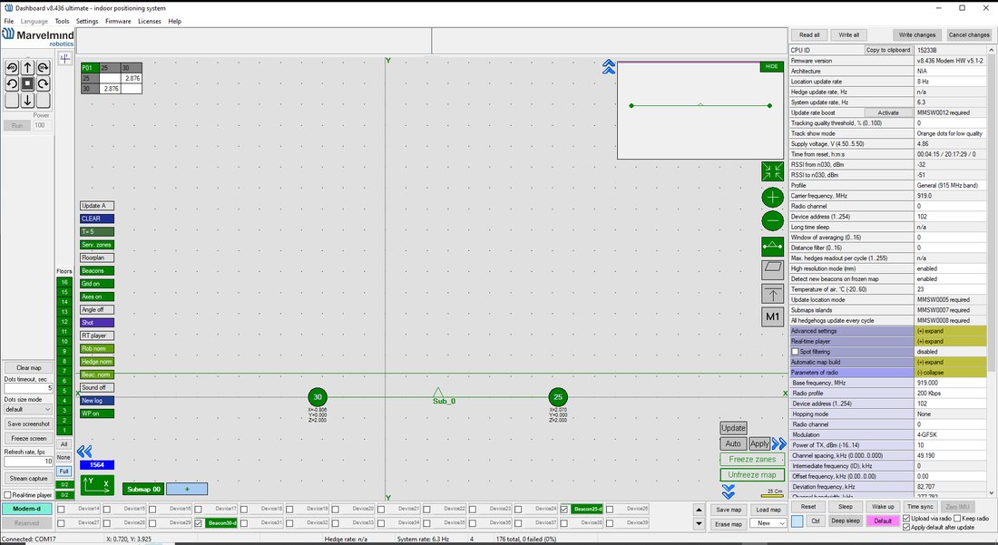 [Updated image]Dashboard is a Windows/Linux/Mac app that sets up and tunes the system and accesses tracking data.
- General app for SW update and initial setting up of the system
- Contains many tracking display features
- Very deep tuning and setting abilities
- All new features available in the Dashboard app
Minimum system requirements:
- OS: Windows 11 64-bit; Linux Ubuntu 18.04
- Processor: Intel Core i5-4200M or equivalent
- Memory: 8 GB RAM
- Display: 1920×1080 pixels
- Storage: 1 GB available space
- Additional Notes: USB 2.0 port
 You can get data without the Dashboard; the whole system can work without it after setting it up. You don’t need a computer, internet access, or cloud to run the system. All calculations are spread between the modem and the beacons.
Stationary Beacon
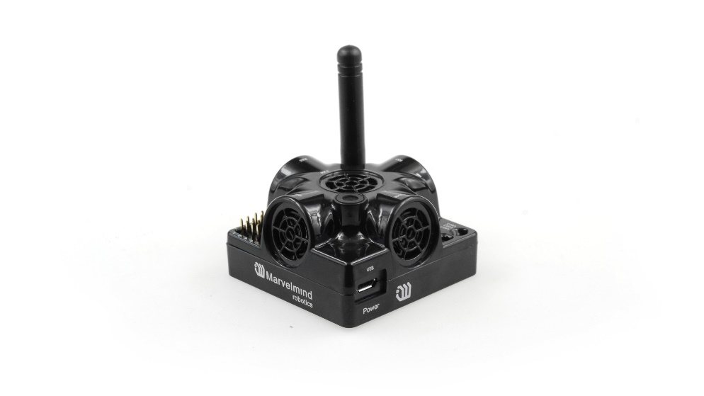 Usually mounted on walls or ceilings above the robot with ultrasonic sensors facing down-to provide the robot’s most robust unobstructed ultrasonic signal coverage. However, for automatic landing and indoor navigation of copters, for example, it is recommended to install a mobile beacon horizontally on the belly of the copter so that the beacon would be looking downwards
Fig.1: Super-Beacon as an example
- For detailed beacon placement guidelines, see the Placement Manual.
- Stationary beacons emit and receive ultrasound during the map configuration period. In non-inverse architecture, they only work as receivers once the map is formed and frozen. In inverse architecture, they only work as transmitters.
- Stationary beacons have no exterior differences from mobile beacons
- The mobile and stationary beacons can be easily interchanged during configuration in the Dashboard
- There are 433 MHz (out of production, get bug-fixing SW update only) and 868/915 MHz versions available. A proprietary radio protocol is used for communication and synchronization. Other ISM bands are available upon request as well
- A stationary beacon can be equipped with a full-size 165 mm antenna, which provides a more robust radio connection between the modem and beacons.
 The mobile and stationary beacons can be easily interchanged by selecting in the Dashboard
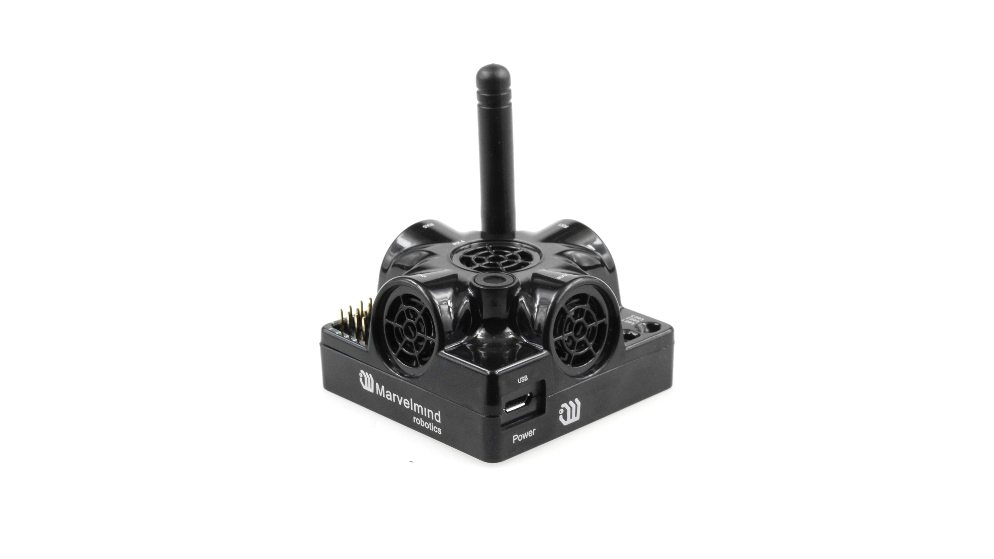 The mobile and stationary beacons can be easily interchanged by selecting in the Dashboard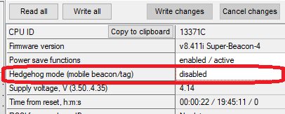
- The mobile beacons are designed to be placed on a robotic vehicle, copter/drone, AGV, or helmet to trace its location. Formally speaking, the location of the mobile beacon is traced-not the robot itself. Since the sizes and the location of the central point of the mobile beacon and the robot are different, the difference is taken into account in the robot’s software (SW)
- It is recommended to place the mobile beacon horizontally to provide optimal ultrasonic coverage in the upper hemisphere
Fig.1: Super-Beacon as an example
- Its sensors must not be covered with anything that can reduce the strength of the ultrasonic signal. For example, the system won’t work well if one puts the mobile beacon in a plastic box
- The beacon’s coordinates are updated according to the rate set on the Dashboard
 The system may contain one or several mobile beacons. The current implementation relies on a time-division multiple access approach and refers only to NIA or MF NIA. Thus, if two mobile beacons are activated, they share the same system bandwidth. It means that if the 16 Hz update rate is selected in the Dashboard and there are 2 mobile beacons in the system, each beacon’s location will be updated with the rate of 16 Hz/2 ~ 8 Hz. If there are 3 mobile beacons => 16 Hz/3 ~ 5 Hz, etc. For 4 and more mobile beacons, we recommend using Inverse Architecture. See more in the architecture comparison. To increase the update rate, see the location update rate boost. and other recommended steps: how to increase location update rate
- Location data is obtained either from the “hedgehog” via USB (virtual UART), UART, SPI, or from the modem via USB (virtual UART). More information on interfaces can be found here (Mini-TX Beacons do not have pinouts, only over micro USB. This doesn’t refer to Mini-TX 2)
- Data from the beacon sent in a streaming format identical to that of GPS (NMEA 0183),U-Blox, or Marvelmind protocol, according to selection in the dashboard
 The system may contain one or several mobile beacons. The current implementation relies on a time-division multiple access approach and refers only to NIA or MF NIA. Thus, if two mobile beacons are activated, they share the same system bandwidth. It means that if the 16 Hz update rate is selected in the Dashboard and there are 2 mobile beacons in the system, each beacon’s location will be updated with the rate of 16 Hz/2 ~ 8 Hz. If there are 3 mobile beacons => 16 Hz/3 ~ 5 Hz, etc. For 4 and more mobile beacons, we recommend using Inverse Architecture. See more in the
  Location data is obtained either from the “hedgehog” via USB (virtual UART), UART, SPI, or from the modem via USB (virtual UART). More information on interfaces can be found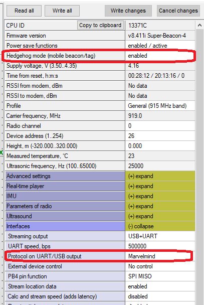
- There are 433 MHz (out of production, get bug-fixing SW update only) and 868/915 MHz versions available. Proprietary radio protocol is used for communication and synchronization
- The “hedgehog” has been successfully integrated with Windows PC, Linux machines, Raspberry Pi, Arduino boards, Intel boards, etc.
Modem
- The modem is the central controller of the system. It must always be powered when the Navigation System is working. An active USB hub or even a regular cellular phone USB power supply is recommended for that purpose. A USB power bank can also be used
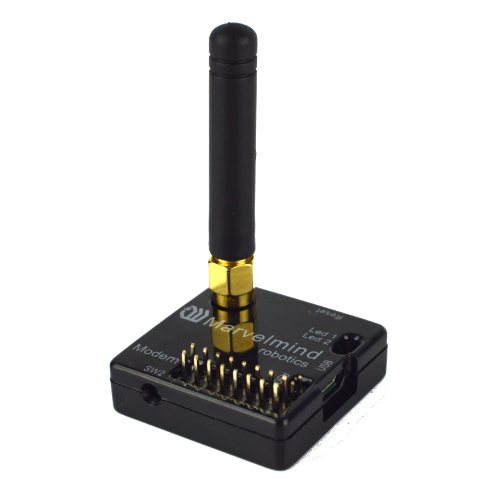
Fig.1: Modem HW v5.1 as an example
- The modem is also used to set up the system, monitor it, and interact with the Dashboard
- It can be placed anywhere within radio coverage for a permanent radio connection with all beacons-usually in a radius of up to 100 meters with antennas from the Starter Set
- Radio coverage was further extended to a few hundred meters by using a lower bitrate of 38 kbps and full-size (165 mm for a 433 and 915 MHz band) antennas, which have been tested to provide up to 400m in ideal conditions
- There are 433 MHz (only for HW v4.9, out of production, get bug-fixing SW update only) and 868/915 MHz versions available
- A proprietary radio protocol used for communication and synchronization between the modem and the beacons
- Modem can stream out location and other data of all mobile beacons via USB and UART using NMEA0183 or Marvelmind protocol, according to selection:
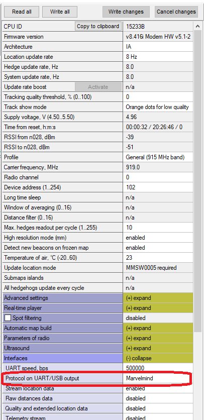
Different Types of Modems
There are three types of Marvelmind modems:
- Modem HW v5.1 – newest and primarily used version of modem
- Modem HW v 4.9 – old version of Modem HW v5.1. Out of production, get bug-fixing SW update only
- Super-Modem – is a superior version of the Modem HW v5.1 with advanced capabilities and interfaces
Super-Modem

Super-Modem is a superior version of the Modem HW v5.1 with advanced capabilities.
Fig.2: Super-Modem’s contents of delivery
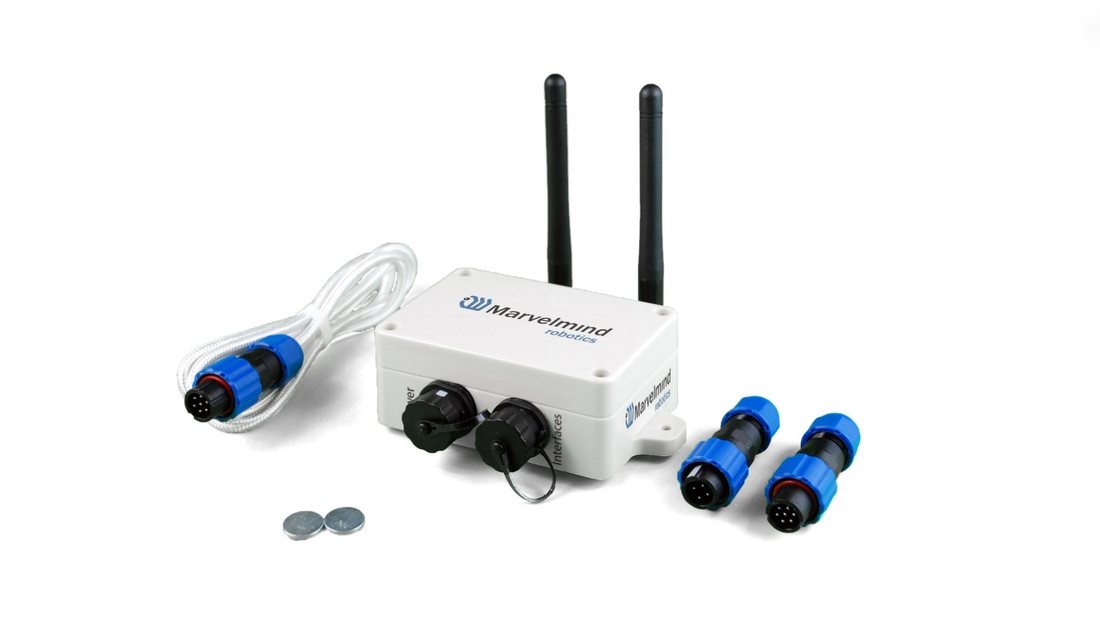
- Super-Modem supports all the basic features of the Modem HW v5.1 and can be connected over USB to the Dashboard for system tuning and control (Do not forget to power the Super-Modem via a Power connector) New Super-Modems also support USB power supply.
- UDP streaming over Wi-Fi – license MMSW0016 – receive coordinates and other data to user-specified IP/port. Details in the ‘Protocols of communication via UDP (Wi-Fi)’ chapter of the Interfaces document. Streaming example: here.
- Marvelmind API via UDP – license MMSW0014 – control Super-Modem via UDP from user software. Details in the ‘Marvelmind API’ chapter of the Interfaces document. API application example: link.
- Bluetooth (HW enabled but not yet supported in SW)
- >1000x more RAM and >1000x Flash memory than Modem HW v4.9
- Full-size bendable antenna by default
- Higher ingress protection – up to IP67 (optional)
- Super-Modem’s HW supports Super-Modem and Super-Super-Modem functionality for Multi-Modem architecture:
 Super-Modem’s HW supports Super-Modem and Super-Super-Modem functionality for Multi-Modem architecture:
- Designed for outdoor and industrial applications
- External bendable antennas with SMA connector for extended radio range included
- Currently, it supports a license-free 915 MHz ISM band (for example, US, Japan, Korea) and a license-free SRD band 868 MHz (EU, Russia). Future 433 MHz HW variants may come in some months, but there is no firm schedule yet. You can place orders for 433 MHz. When enough orders are collected, we will produce the 433 MHz version as well
- Supports all types of beacons working in the 915 MHz band (among them: Super-Beacons, all Industrial beacons, Mini-RX, Beacons HW v4.9, Helmets, Badges, Jackets, Watches, etc.)
- Two IP67 external connectors included (like Industrial beacons):
+5 V in (5)
+5 V in (3)
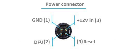
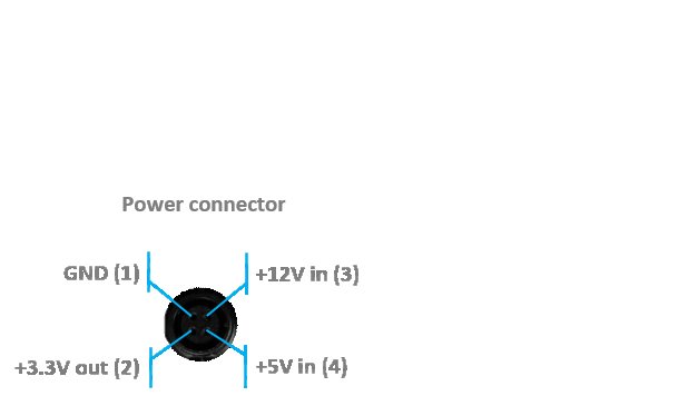
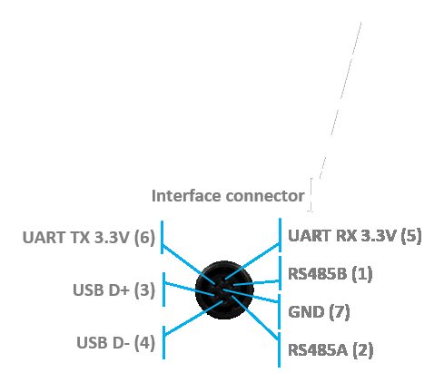
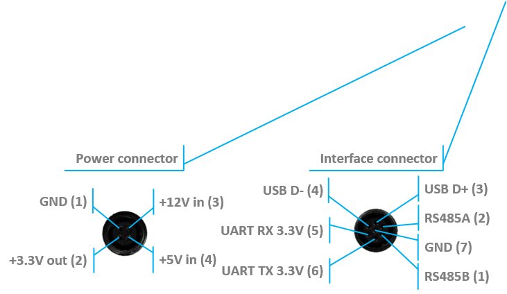
- The same mounting holes as for Industrial beacons
- No battery inside – external power supply (+5 V) required (for example, Converter-AC-5 V-IP67). External battery is not practical for long-term due to relatively high and constant power consumption of 1.5-2W
 The new version of Super-Modem (from June 2023) supports ONLY a +5 V power supply. Please don’t use a +12 V power supply converter for this version; it will burn the beacon!
- For optional IP67 version – extended working temperature range: -40C…+50C (provided by design – not tested, not certified)
- Embedded reset switch and DFU switch – magnetic control or external pins on IP67
- Supports IA, NIA, and MF NIA. Can be easily switched between the modes in the Dashboard
 No battery inside – external power supply (+5 V) required (for example,
  The new version of Super-Modem (from June 2023) supports ONLY a +5 V power supply. Please don’t use a +12 V power supply converter for this version; it will burn the beacon!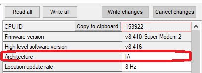
- Radio range to beacons – up to a few hundred meters in the open space area. Wi-Fi – a few tens of meters in the open space
Modem HW v5.1
Modem HW v5.1 is a superior version of the Modem HW v4.9.
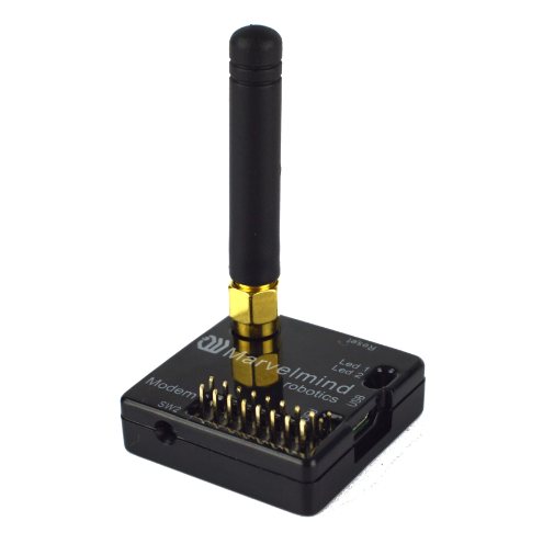
Fig.1: Modem HW v5.1
 Modem HW v5.1 looks almost the same as Modem HW v4.9. To distinguish it, check the white sticker on the bottom.
Modem HW v5.1 and Modem HW v4.9 brief comparison:
Modem HW v5.1 has more memory
Modem HW v5.1 has a higher radio range
Modem HW v5.1 more sensitive
Modem HW v5.1 has TELEC T-108 Japan certification
All new features come to the new Modem HW v5.1
FCC NOTICE:
This equipment has been tested and found to comply with the limits for a Class B digital device, pursuant to Part 15 of the FCC Rules. These limits are designed to provide reasonable protection against harmful interference in a residential installation. This equipment generates, uses, and can radiate radio frequency energy and, if not installed and used in accordance with the instructions, may cause harmful interference to radio communications. However, there is no guarantee that interference will not occur in a particular installation. If this equipment does cause harmful interference to radio or television reception, which can be determined by turning the equipment off and on, the user is encouraged to try to correct the interference by one or more of the following measures:
Reorient or relocate the receiving antenna
Increase the separation between the equipment and the receiver
Connect the equipment to an outlet on a circuit different from that to which the receiver is connected
Consult the dealer or an experienced radio/TV technician for help
Changes or modifications not expressly approved by the party responsible for compliance could void the user’s authority to operate the equipment.
This device complies with part 15 of the FCC Rules. Operation is subject to the following two conditions:
(1) This device may not cause harmful interference, and
(2) This device must accept any interference received, including interference that may cause undesired operation.
The equipment should be installed and operated with a minimum distance of 20 cm between the radiator & your body.
Modem HW v4.9 (Superseded by the Modem HW v5.1)
Modem HW v4.9 has balanced features and performance. See the Beacon HW v4.9.
 Since Modem HW v5.1 was released, Modem HW v4.9 will only get bug-fixing SW updates.
- The modem is also used to set up the system, monitor it, and interact with the Dashboard
- It can be placed anywhere within radio coverage for permanent radio connection with all beacons-usually in a radius of up to 100 meters with antennas from the Starter Set
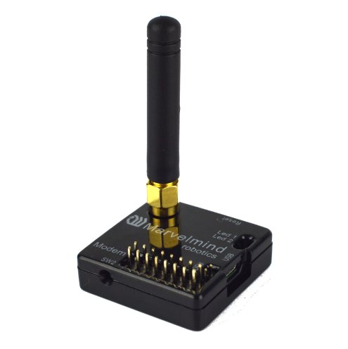
Fig.1: Modem HW v4.9
- Radio coverage is further extended to a few hundred meters by using a lower bitrate of 38 kbps and full-size (165 mm for a 433 MHz band) antennas, which have been tested to provide up to 400m in ideal conditions
- There are 433 MHz and 915 MHz versions available
- A proprietary radio protocol used for communication and synchronization between modem and beacons
Different Types of Beacons
There are many types of beacons. Each is used in different ways, depending on your case and preferences.
- Mini-RX – can receive ultrasound and is mainly used as a mobile beacon. It could be made in Outdoor modification
- Mini-TX – for ultrasound transmitting only. Because of its small size, it is suitable for copter and tracking
- Super-Beacon – can receive and transmit ultrasound, using in most cases. It could be made in Outdoor modification
- Industrial-RX – suitable for massive manufacturing and outdoor installation. It has no sensors and works in NIA architecture as a stationary beacon or mobile beacon in IA architecture
- Industrial Super-Beacon– a fully functional Super-Beacon that can work as a mobile and stationary beacon. It is suitable for massive manufacturing and outdoor installation

Here you can see more details about the different types of beacons.
Super-Beacon
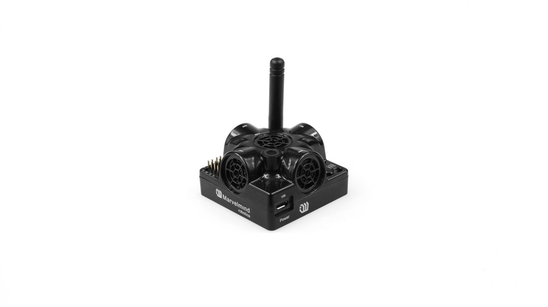 The Super-Beacon is a dual-use beacon – it can both receive and transmit ultrasonic pulses.
 The Super-Beacon can be used in the Non-Inverse Architecture (NIA), Multi-Frequency NIA (MF NIA), and the Inverse Architecture (IA): Architecture comparison.
It supports a license-free 915 MHz ISM band (US) and a license-free SRD band of 868 MHz (EU). Support of the 433 MHz ISM band (EU) comes with a larger order.
Key features:
- The Super-Beacon has a separate receiving part with a single wide-beam microphone and sharp DSP filters (like Mini-RX or Industrial-RX has). Thus, it is more sensitive than Beacon HW v4.9, more resistant to external noise, and easier to set because you don’t have to care about turning on and off ultrasonic sensors to optimize coverage vs. sensitivity
- The Super-Beacon can transmit one of the following ultrasonic frequencies: 19 kHz, 22 kHz, 25 kHz, 28 kHz, 31 kHz, 34 kHz, 37 kHz, or 45 kHz. The frequency is defined by hardware and is specified on the sticker on the bottom of the beacon. This frequency is also shown in the beacon’s settings in the Dashboard. Important: do not change this setting – keep it the same as specified on the sticker.
- The Super-Beacon can receive any ultrasonic frequency from the following bands: 19 kHz, 22 kHz, 25 kHz, 28 kHz, 31 kHz, 34 kHz, 37 kHz, 45 kHz. This allows the Super-Beacon to receive ultrasonic signals from multiple beacons with different transmit frequencies simultaneously.
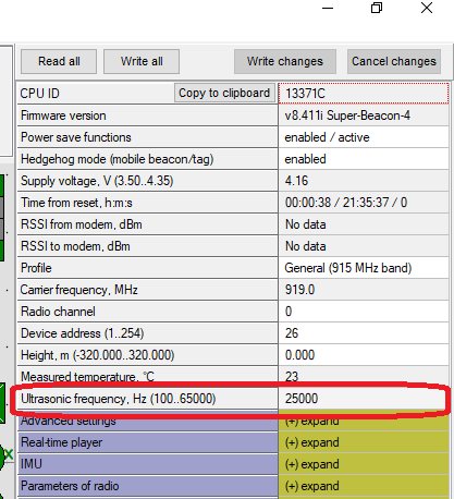
- The Super-Beacon can receive several ultrasonic frequencies at once. This allows beacons transmitting at different frequencies to be tracked in the same submap.
- The Super-Beacon has several-times improved battery lifetime in TX mode as compared with Beacon HW v4.9
- The Super-Beacon can work with regular Beacons HW v4.9 and Mini-RX and Industrial-RX in any combination as a part of a Starter Set or a part of navigation systems. In all cases, beacons shall use the same radio band
 The Super-Beacon can receive several ultrasonic frequencies at once. This allows beacons transmitting at different frequencies to be tracked in the same submap.
 Super-Beacon also has an outdoor (IP54) version, protected from dust and water.
 Demo video: Demo: IP56 testing of Super-Beacon-IPxx
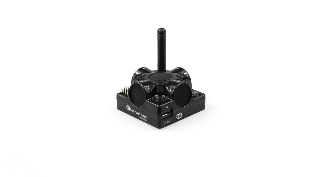
Figure 1: Outdoor version (IP54)
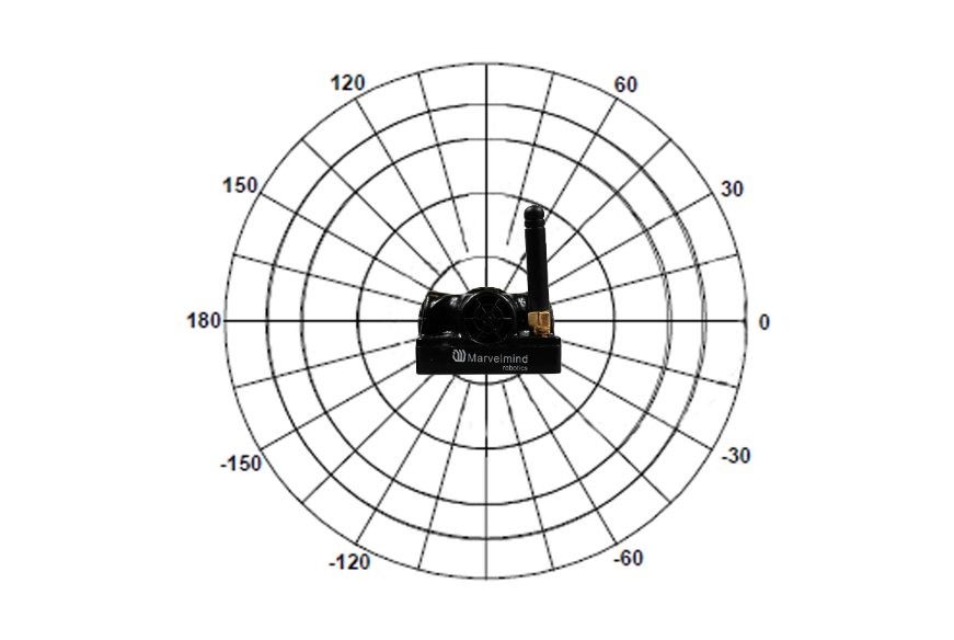
Figure 5: Receiving diagram (with digital microphone)
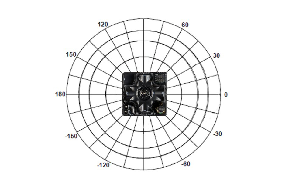
Figure 4: Receiving diagram (with digital microphone)
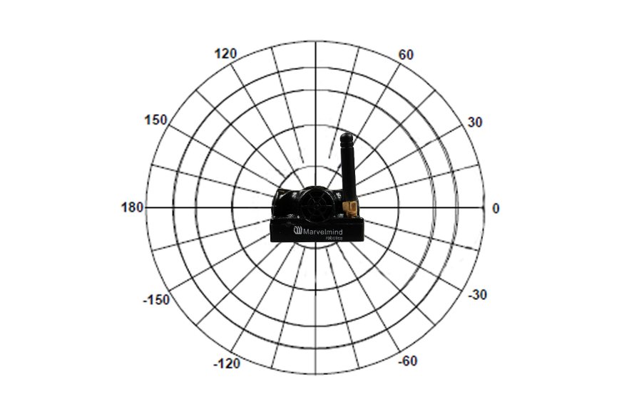
Figure 3: Transmitting diagram (with ultrasound transmitters)
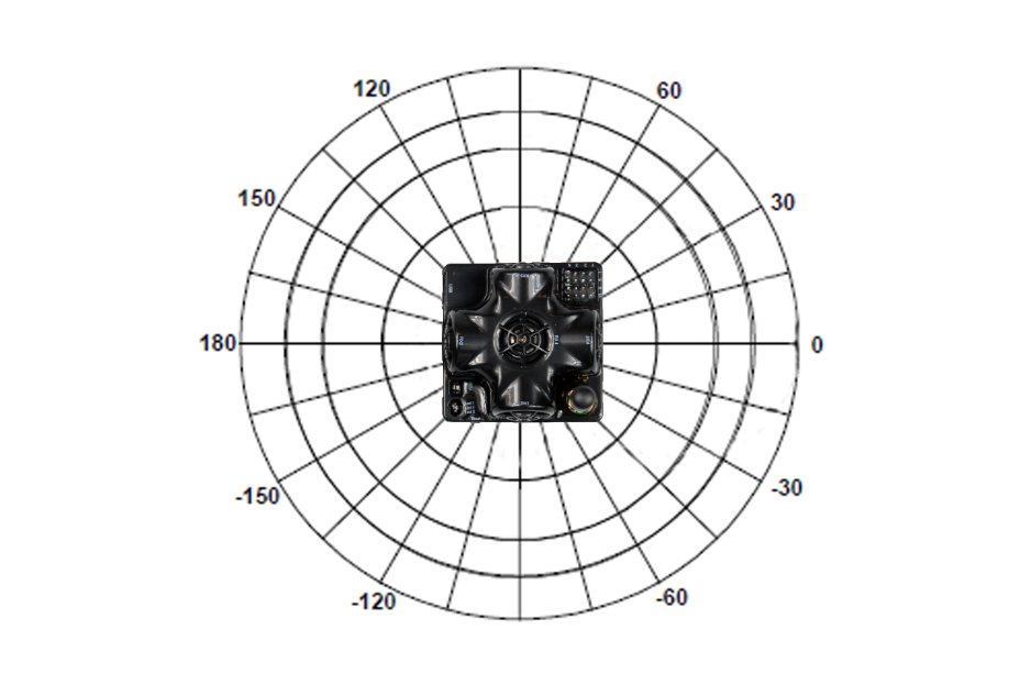
Figure 2: Transmitting diagram (with ultrasound transmitters)
FCC NOTICE:
This equipment has been tested and found to comply with the limits for a Class B digital device, pursuant to Part 15 of the FCC Rules. These limits are designed to provide reasonable protection against harmful interference in a residential installation. This equipment generates, uses, and can radiate radio frequency energy and, if not installed and used in accordance with the instructions, may cause harmful interference to radio communications. However, there is no guarantee that interference will not occur in a particular installation. If this equipment does cause harmful interference to radio or television reception, which can be determined by turning the equipment off and on, the user is encouraged to try to correct the interference by one or more of the following measures:
- Reorient or relocate the receiving antenna
- Increase the separation between the equipment and the receiver
- Connect the equipment to an outlet on a circuit different from that to which the receiver is connected
- Consult the dealer or an experienced radio/TV technician for help
Changes or modifications not expressly approved by the party responsible for compliance could void the user’s authority to operate the equipment.
This device complies with part 15 of the FCC Rules. Operation is subject to the following two conditions:
(1) This device may not cause harmful interference, and
(2) This device must accept any interference received, including interference that may cause undesired operation.
The equipment should be installed and operated with a minimum distance of 20 cm between the radiator & your body.
Beacon Mini-RX
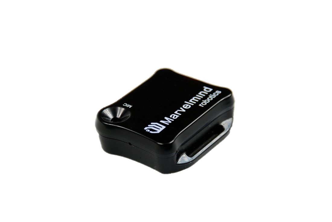 The Beacon Mini-RX can be used in the Inverse Architecture (IA) as a mobile beacon and in the Non-Inverse Arc
 hitecture (NIA) and in the Multi-frequency Non-Inverse Architecture (MF NIA) as a stationary beacon: NIA, IA, and MF NIA comparison.
In the majority of cases, Mini-RX is used along with one or more external microphones because they provide the best possibility for the line of sight between the mobile beacon (Mini-RX + external microphones) and stationary beacons.
- Mini-RX is an RX-only beacon, i.e., it can receive, but it cannot transmit an ultrasonic signal
- The Mini-RX beacon can receive any ultrasonic frequency from the following bands or all at once: 19 kHz, 22 kHz, 25 kHz, 28 kHz, 31 kHz, 34 kHz, 37 kHz, and 45 kHz.
- The Mini-RX Beacon is significantly smaller and lighter than Super-Beacon. It is it’s the main advantage
- It can play the role of a stationary beacon when imputing coordinates manually (in NIA and MF NIA)
- It can play the role of a mobile beacon (in an IA system)
- It has a digital microphone, which is more sensitive than regular sensors
- Supports 868/915 MHz radio license-free ISM/SRD bands
- Can be water-protected
- Mini-RX is at the heart of Marvelmind Helmet, Jacket, Headlight, Watch, and Badge
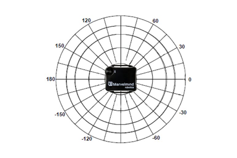
- It has 360° reception angle (horizontally) and 120° reception angle (vertically)
 Can be
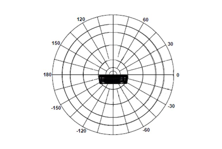
 Reception diagram. The digital microphone’s reception angle is about 360° (horizontally) and 180° (vertically) (if used without housing) and 360°x120° with the housing.
 Mini-RX beacon may be over-discharged. In that case, do the following:
Please turn off the beacon with DIP switches and charge it for 1 hour. Then turn the beacon on, flash the latest SW via DFU Programming, and charge it for 1 hour again
How to Flash Beacon Mini-R X
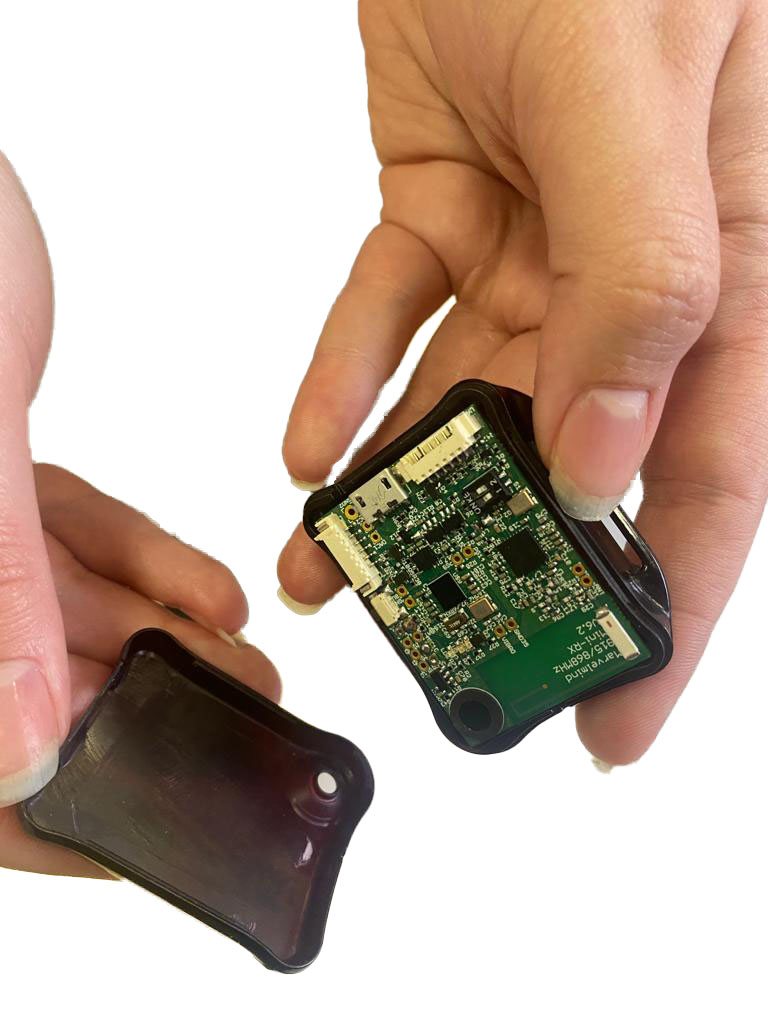
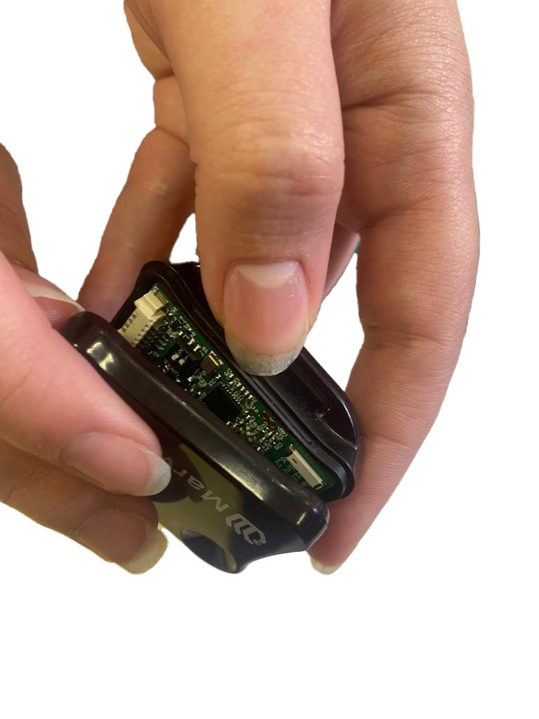
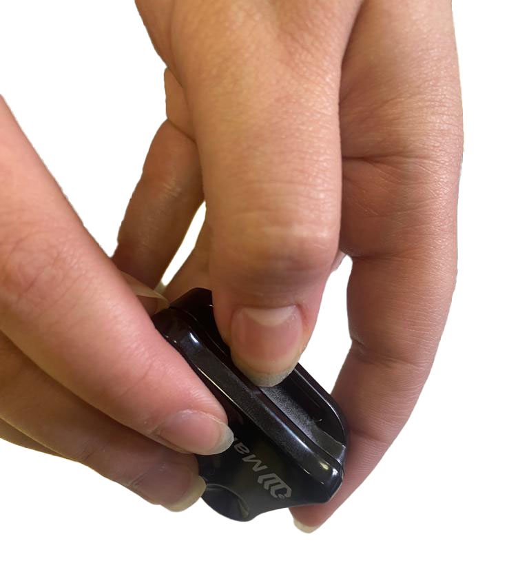 When you receive Beacon Mini-RX, it is turned off. Open it to access the DIP switch.

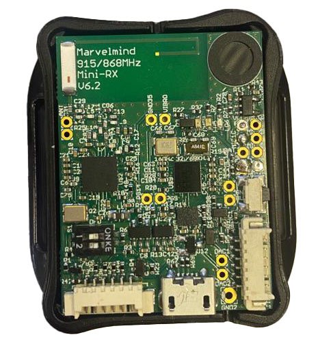 Only charging the device is possible when the DIP switch is in this position.
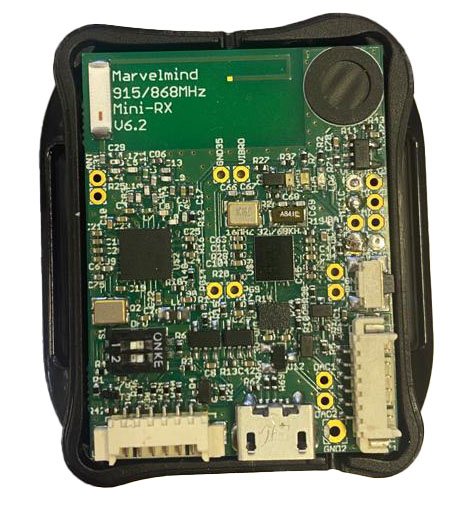 For HEX programming (via Dashboard)

 Put DIP switch to this position:
For DFU programing (via: DfuSe v3.0.5 or DfuSe v3.0.6)
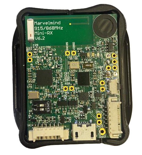
Beacon Mini-TX
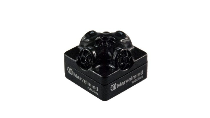 The Mini-TX is a TX-only beacon, i.e., it can transmit but cannot receive an ultrasound.
Comparison to Super-Beacon:
- Smaller size and lighter: 47x42x15 mm & 25g vs. 55x55x33 mm & 62g (or 55x55x64 mm with antenna)
- TX only, i.e., Mini-TX can only transmit ultrasonic and cannot receive. Super-Beacon is dual use: it can receive and transmit ultrasonic
- Only has 31 kHz version
- Battery – 250mAh vs. 1000mAh in a regular beacon. But Mini-TX has a new, more efficient ultrasonic TX module; thus, battery lifetime in TX mode is even superior to the Beacon HW v4.9
- Tested battery lifetime with 8 Hz – 96h. With a lower update rate – nearly proportionally longer. Very efficient ultrasonic TX module
- Mini-TX has only USB (virtual UART) output – no additional pins. This doesn’t refer to Mini-TX 2.
- Mini-TXs have embedded IMU – it has a 3D accelerometer and 3D gyroscope, but no magnetometer (which we do not recommend using indoors anyway, due to magnetic field distortion)
- Embedded antenna – smaller size, but smaller radio coverage ~50m with regular Modem HW v5.1 as compared with ~100m of Super-Beacon with Modem HW v5.1
- Ultrasonic range is virtually on par with regular Super-Beacon – up to 30m with Super-Beacon as RX beacon. At the same time, for example, a combination of Mini-RX RX beacon + Mini-TX TX provides better coverage and a stronger signal than Super-Beacon + Super-Beacon
- This HW is for the 868/915 MHz band only, i.e. 433 MHz is not supported and not planned
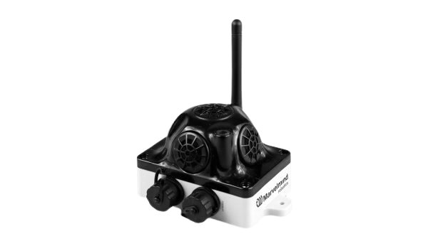
Industrial Super-Beacon-Plastic
Do not disassemble the Industrial beacons. Otherwise, the warranty will be lost
 TX-only beacon – can transmit ultrasonic, but can’t receive it
- Electronics is IP55 protected
- Special 16 mm ultrasonic transducers protected by special membranes
- The same RX and TX frequencies as on normal Super-Beacon
- External antenna with SMA connector for extended radio range
- Corresponding IP55 connectors (male part) included
- No battery inside
- Extended working temperature ranges from -40°C to +50°C (not tested, provided by design)
- Embedded reset switch and DFU switch – magnetic control
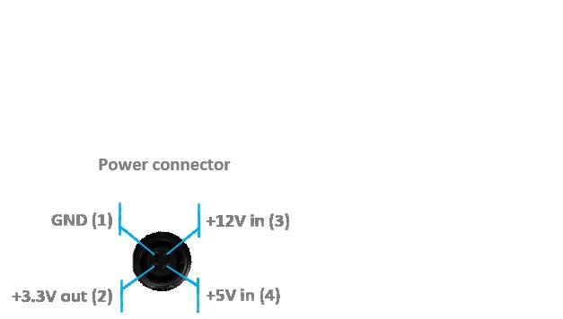
- Two IP55 external connectors:
 Modification (After June 2022) for versions 2, 3, and 4
 TX-only beacon – can transmit ultrasonic, but can’t receive it
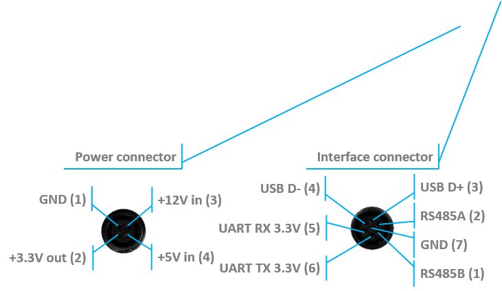 Modification (After June 2022) for versions 2, 3, and 4
+5 V in (3)
+5 V in (5)
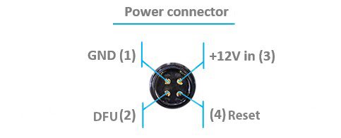
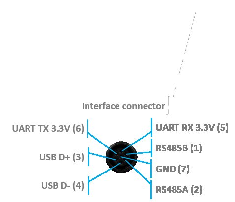
Version 2 and 3 of Industrial-TX-Metal (from June 2022) support a +5 V power supply ONLY. Don’t use a +12 V power supply converter for this version, it will burn the beacon!
Starting from version 4 Industrial Super-Beacon-Plastic for Pin 5 in 7-pin connector jumper is connected by default. So, you get +5 V but not UART RX. However, if you don’t connect the 7-pin USB cable you can get UART RX. If you want to be on the very safe side you can completely remove the jumper. For more information contact us via info@marvelmind.com
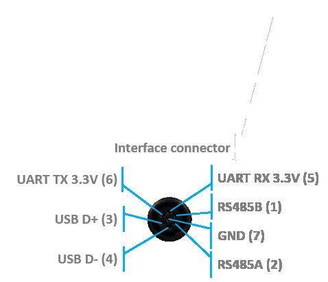
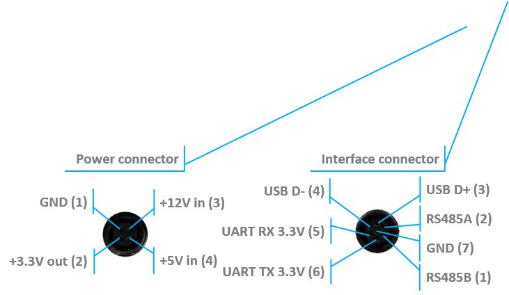
- Industrial beacons can communicate with Super-Modem via RS-485 instead of radio. See: RS485 Instead of Radio.
- RS485 modification pinouts (After Sep.2019)
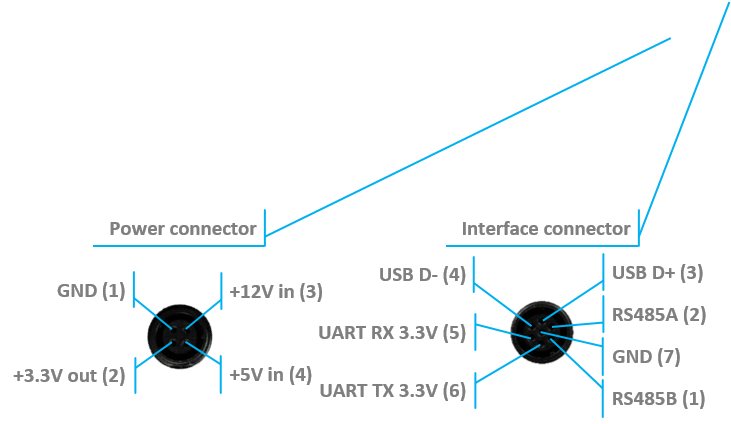 RS485 modification pinouts (After Sep.2019)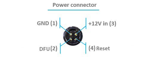
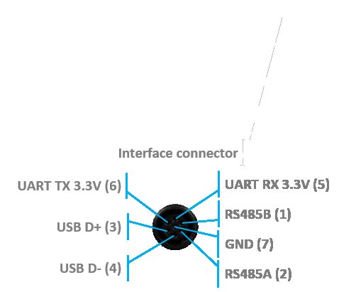
- RS485 modification pinouts (Before Sep.2019)
 RS485 modification pinouts (Before Sep.2019)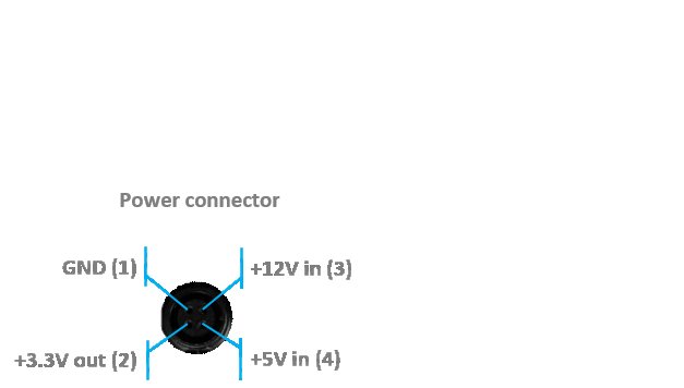
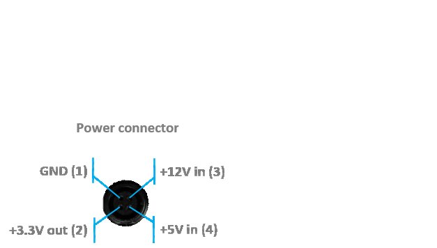
- CAN modification pinouts
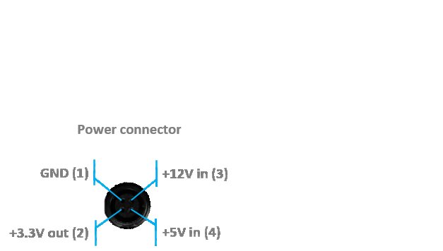
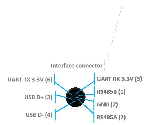
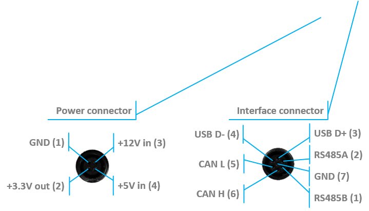
- Can work with any Mini-RX beacon or Super-Beacon
- Most of all, designed to work together with Outdoor versions of Mini-RX beacons and heavy outdoor Industrial-TX and Industrial-RX beacons (radio bands must match)
- Up to 30m with Beacon Mini-RX
- Optional external Converter-220 V-12 V-IP67 (except version from April 2022, it supports only +5 V power supply)
 Wide transmitting diagram
 Most of all, designed to work together with
  Optional external
 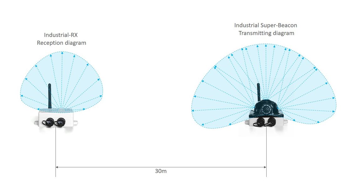 Wide transmitting diagram
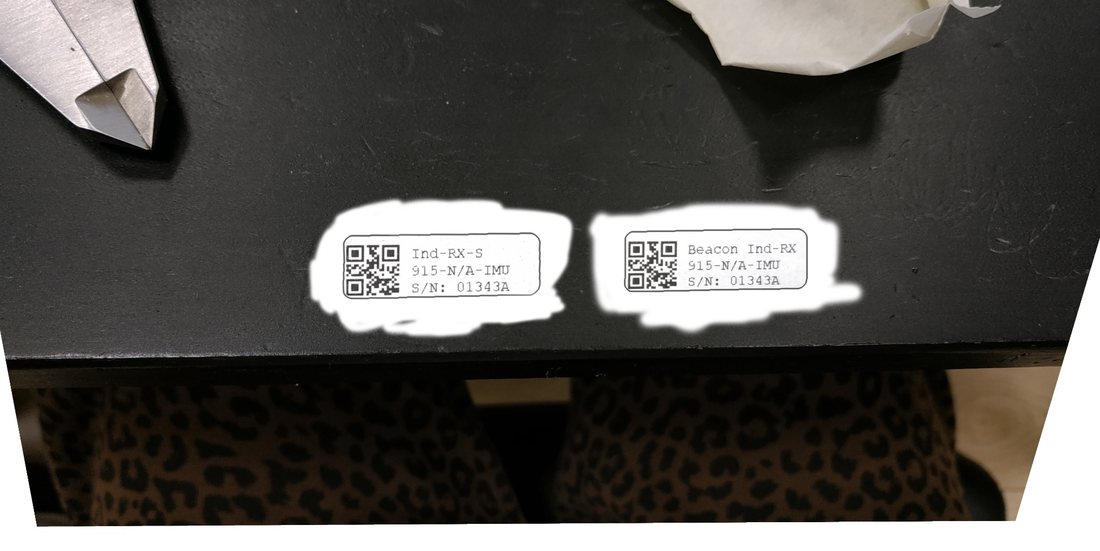
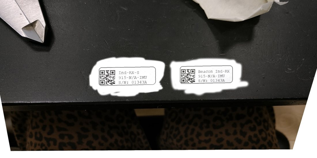
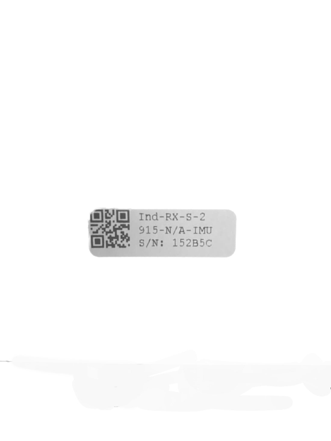
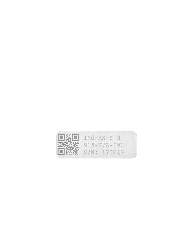
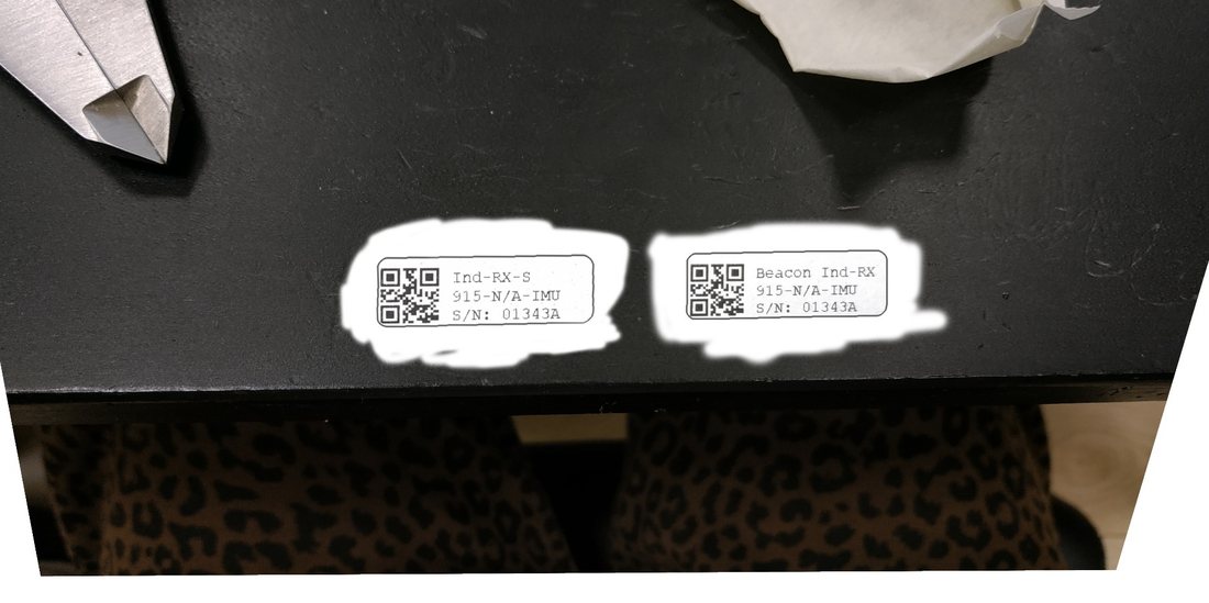 Determine carefully the version of your Industrial beacons: they may be built before September 2019 and after September 2019. If it is a beacon from the late batch, you must use Industrial Super-Beacon SW. If you have beacons from the early batch, use Industrial-RX or Industrial-TX SW. Stickers’ differences: Later batch – Ind-RX-S or Ind-TX-S. Early batch – Beacon Ind-RX or Beacon Ind-TX.
 Versions 2 and 3 of Industrial-TX-Metal (from June 2022) support ONLY +5 V power supply. Don’t use a +12 V power supply converter for this version, it will burn the beacon!
Beacon Industrial-RX
Do not disassemble the Industrial beacons. Otherwise, the warranty will be lost
 RX-only beacon – can receive ultrasonic, but can’t transmit it
- Electronics is IP67 protected
- Special IP67 membrane for ultrasonic sensor
- External antenna with SMA connector for extended radio range
- Corresponding IP67 connectors (male part) included
- No battery inside by default – external power bank or external power supply (+12 V or +5 V). But an optional variant with an internal battery is possible (except the version from April 2022, which supports only a +5 V power supply)
- Two IP67 external connectors:
- Modification (After April 2022)
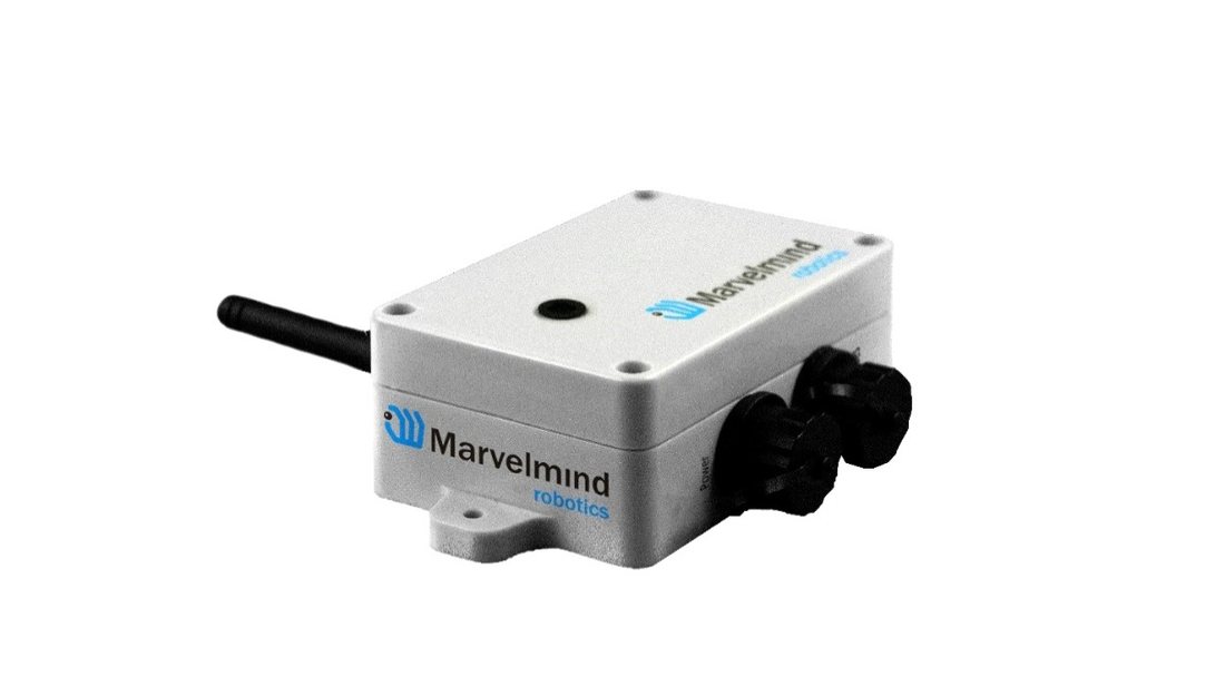 RX-only beacon – can receive ultrasonic, but can’t transmit it
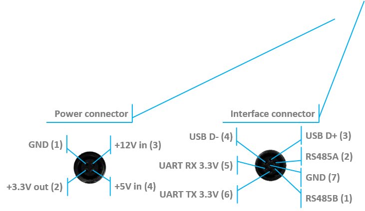 Modification (After April 2022)
+5 V in (5)
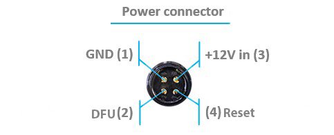
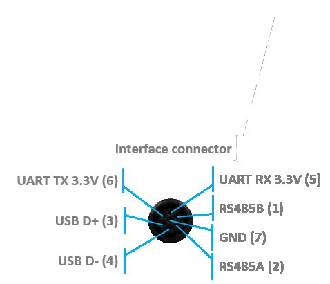
+5 V in (3)
 Version 3 of Industrial RX (from April 2022) supports ONLY a +5 V power supply. Don’t use a +12 V power supply converter for this version; it will burn the beacon!
This version doesn’t have UART RX, but it is now possible to use the Interface connector as a power supply
- Industrial beacons can communicate with Super-Modem via RS-485 instead of radio. See: RS485 Instead of Radio.
- RS485 modification pinouts (After Sep.2019)
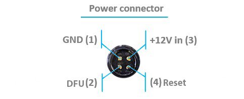
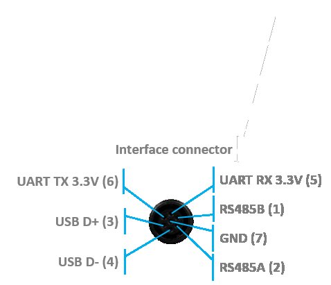
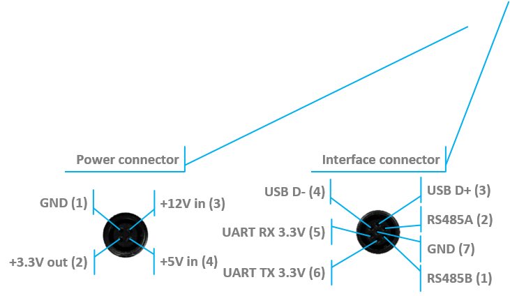
- RS485 modification pinouts (Before Sep.2019)
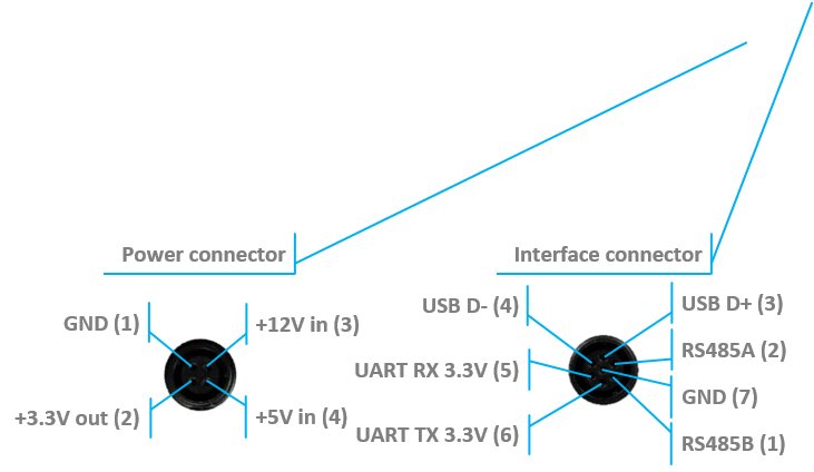 RS485 modification pinouts (Before Sep.2019)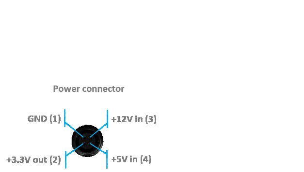
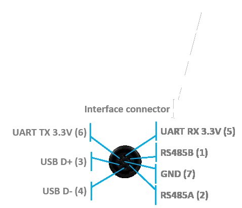
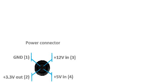
- CAN modification pinouts
- Extended working temperature range from -40°C to +50°C (not tested, provided by design) – only for the version without battery
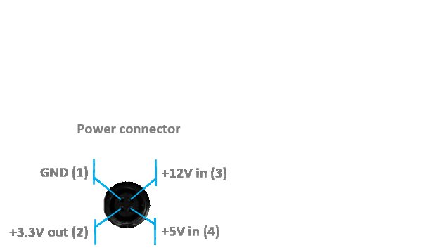
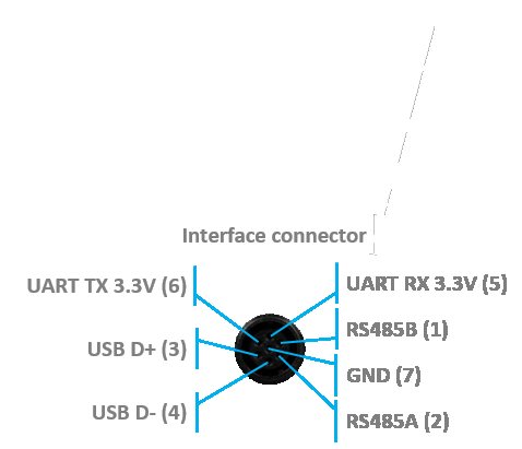
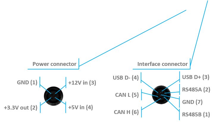
- Embedded reset switch and DFU switch – magnetic control
- Supports a wide range of ultrasonic frequencies: 19/22/25/28/31/34/37/45 kHz
- Most of all, designed to work together with Outdoor versions of Mini-RX beacons and heavy outdoor Industrial-TX and Industrial-RX beacons (radio bands must match)
- Optional external Converter-220 V-12 V-IP67 (except version from April 2022, it supports only +5 V power supply)
- Optional external Converter-AC-5 V-IP67 for versions 2 and 3
- Wide reception diagram
 Most of all, designed to work together with
  Optional external
 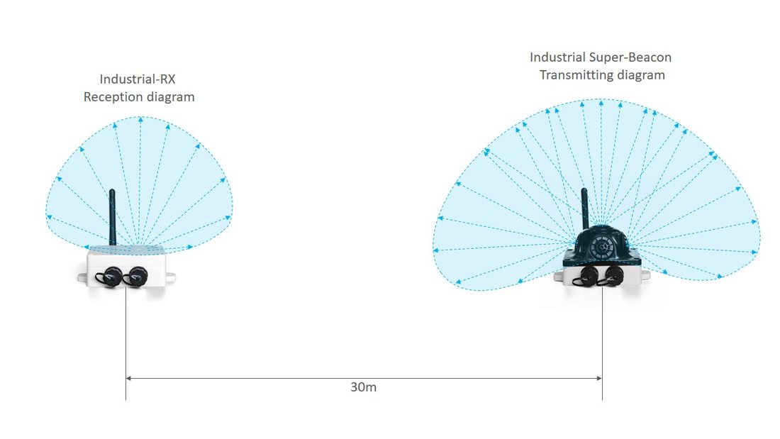 Wide reception diagram
 Uploading Beacon’s Industrial-RX or Beacon’s Industrial-TX SW to Industrial Super-Beacon may permanently damage the Industrial Super-Beacon board.

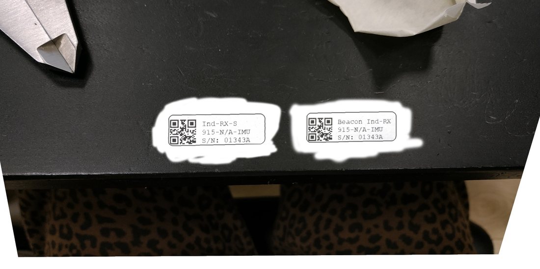 Determine carefully the version of your Industrial beacons: they may be built before September 2019 and after September 2019. If it is a beacon from the late batch, you must use Industrial Super-Beacon SW. If you have beacons from the early batch, use Industrial-RX or Industrial-TX SW. Stickers’ differences: Later batch – Ind-RX-S or Ind-TX-S. Early batch – Beacon Ind-RX or Beacon Ind-TX.
 Versions 2 and 3 of Industrial-TX-Metal (from June 2022) support ONLY +5 V power supply. Don’t use a +12 V power supply converter for this version; it will burn the beacon!
This version doesn’t have UART RX, but it is now possible to use the Interface connector as a power supply.
Industrial Super-Beacon Metal-25 kHz
Do not disassemble the Industrial beacons. Otherwise, the warranty will be lost
- Supports dual-use – RX and TX beacon. It can transmit on its native ultrasonic frequency (25 kHz) and receive on any ultrasonic frequency via an embedded RX sensor – like Industrial-RX or Mini-RX does. Effectively, the Industrial Super-Beacons combine inside an Industrial-TX and Industrial-RX. Additionally, the beacon supports both AI and NIA architectures. Thus, it is called Industrial Super-Beacon
- Electronics is IP67 protected
- Special IP67-protected 25-kHz transducers
- External antenna with SMA connector for extended radio range
- Corresponding IP67 connectors (male part) included
- No battery inside
- Extended working temperature range from -40°C to +50°C (not tested, provided by design)
- Embedded reset switch and DFU switch – magnetic control
- Two IP67 external connectors:

 Modification (After April 2022)
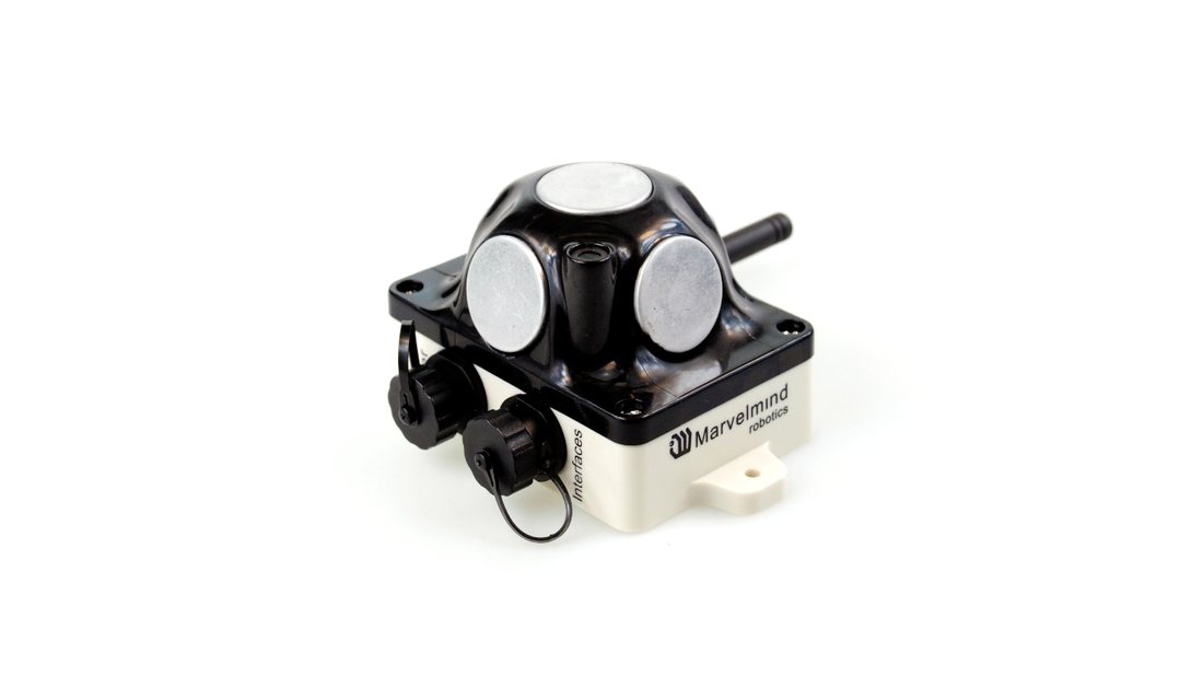 Supports dual-use – RX and TX beacon. It can transmit on its native ultrasonic frequency (25 kHz) and receive on any ultrasonic frequency via an embedded RX sensor – like Industrial-RX or Mini-RX does. Effectively, the Industrial Super-Beacons combine inside an Industrial-TX and Industrial-RX. Additionally, the beacon supports both AI and NIA architectures. Thus, it is called Industrial Super-Beacon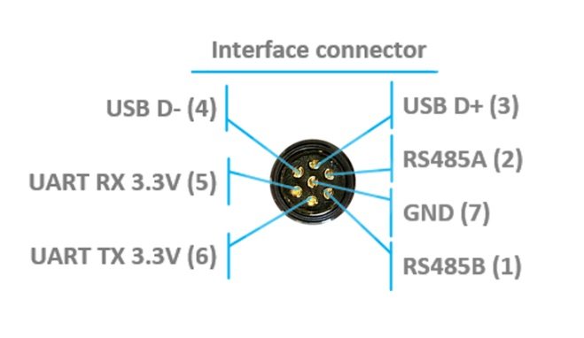
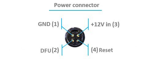 Modification (After April 2022)
 +5 V in (5)
+5 V in (3)
- Version 3 of Industrial RX (from April 2022) supports ONLY +5 V power supply. Don’t use +12 V power supply converter for this version, it will burn the beacon!
- This version doesn’t have UART RX, but now is possible to use Interface connector as a power supply.
- Industrial beacons can communicate with Super-Modem via RS-485 instead of radio. See: RS485 Instead of Radio.
- RS485 modification pinouts
 Version 3 of Industrial RX (from April 2022) supports ONLY +5 V power supply. Don’t use +12 V power supply converter for this version, it will burn the beacon!
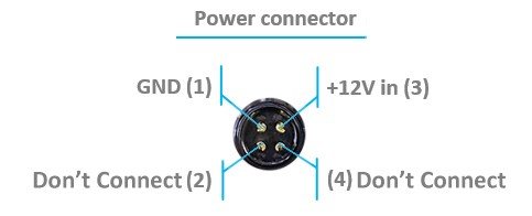 RS485 modification pinouts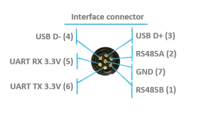
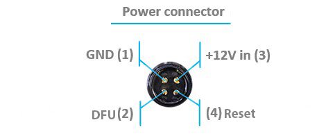
- Can work together with modems with corresponding radio (radio bands must match)
- Can work with any Mini-RX beacon or Super-Beacon
- Most of all designed to work together with Outdoor versions of Mini-RX beacons and heavy outdoor Industrial-TX and Industrial-RX beacons (radio bands must match)
- Up to 30m with Beacon Mini-RX
- Optional external Converter-220 V-12 V-IP67 (except version from April 2022, it supports only +5 V power supply)
 Most of all designed to work together with
  Optional external
  Uploading Beacon Industrial’s (Not super) DFU software to Industrial Super-Beacon hardware make permanently damage for Industrial Super-Beacon board. Be double attentive with update
 Version 2 and 3 of Industrial-TX-Metal (from June 2022) supports ONLY +5 V power supply. Don’t use +12 V power supply converter for this version, it will burn the beacon!
This version doesn’t have UART RX, but now is possible to use Interface connector as a power supply.
Beacon HW v4.9 (Superseded by the Super-Beacon)
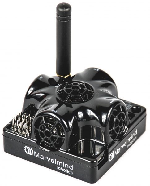
 Beacon HW v4.9 can be used in both the Non-Inverse Architecture (NIA) and the Inverse Architecture (IA): NIA and IA comparison
It can’t be used in MF NIA. In IA, it can work as a stationary beacon and cannot be used as a mobile beacon.
IA | NIA | MF NIA | |
Stationary | Yes | Yes | No |
Mobile | No | Yes | No |
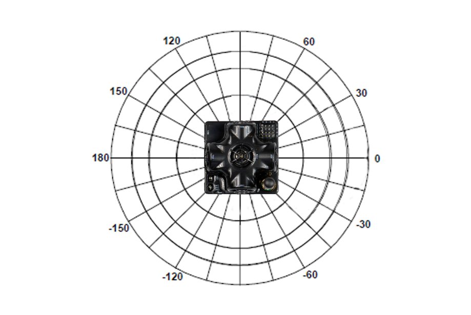
Figure 2: Transmitting diagram (with sensors)
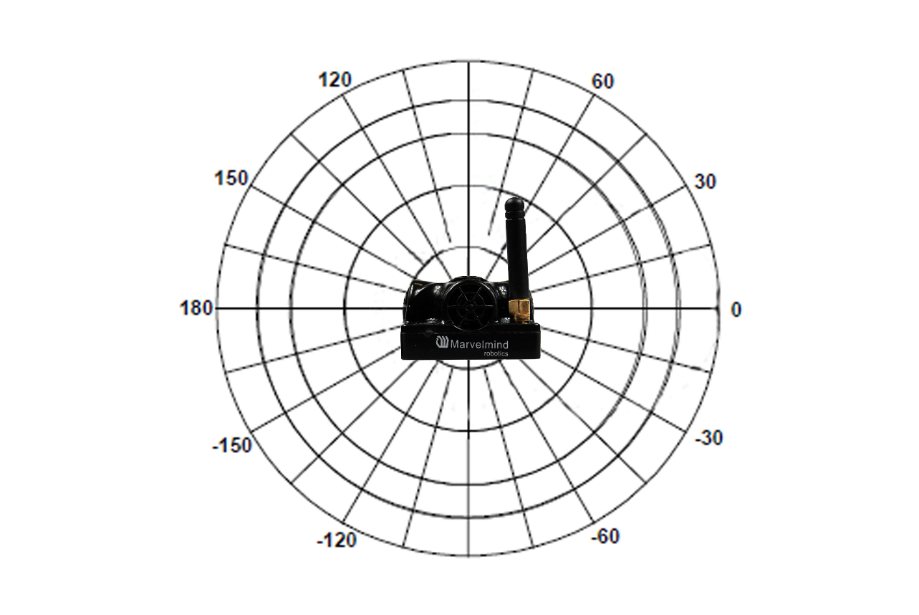
Figure 1: Transmitting diagram (with sensors)
Beacons Transducers Scheme
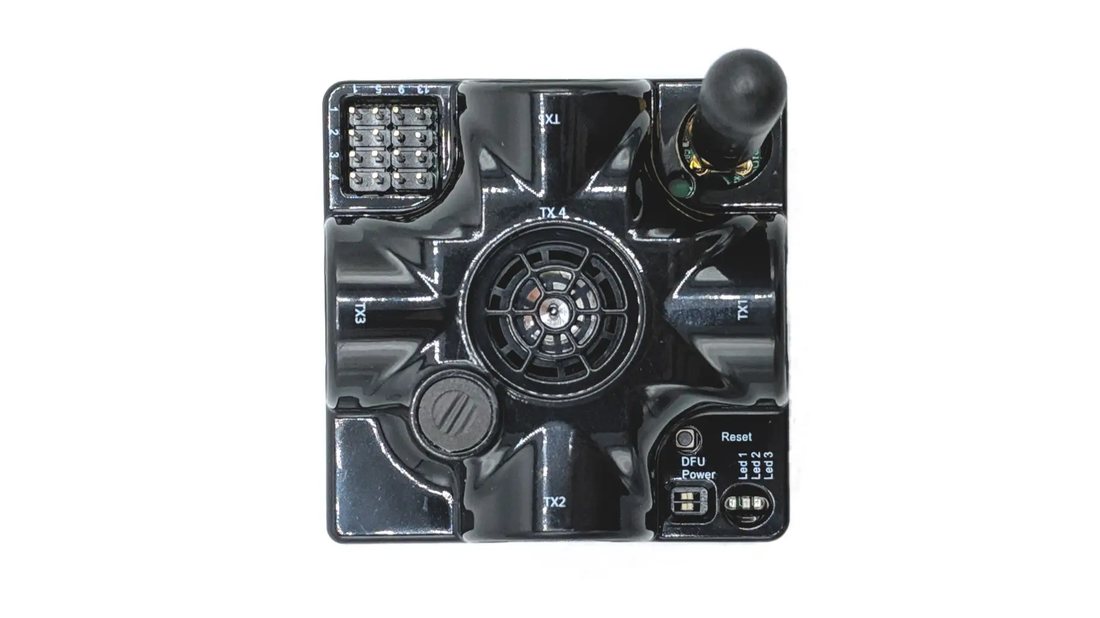
- TX1
- TX2
- TX3
- TX4
- TX5
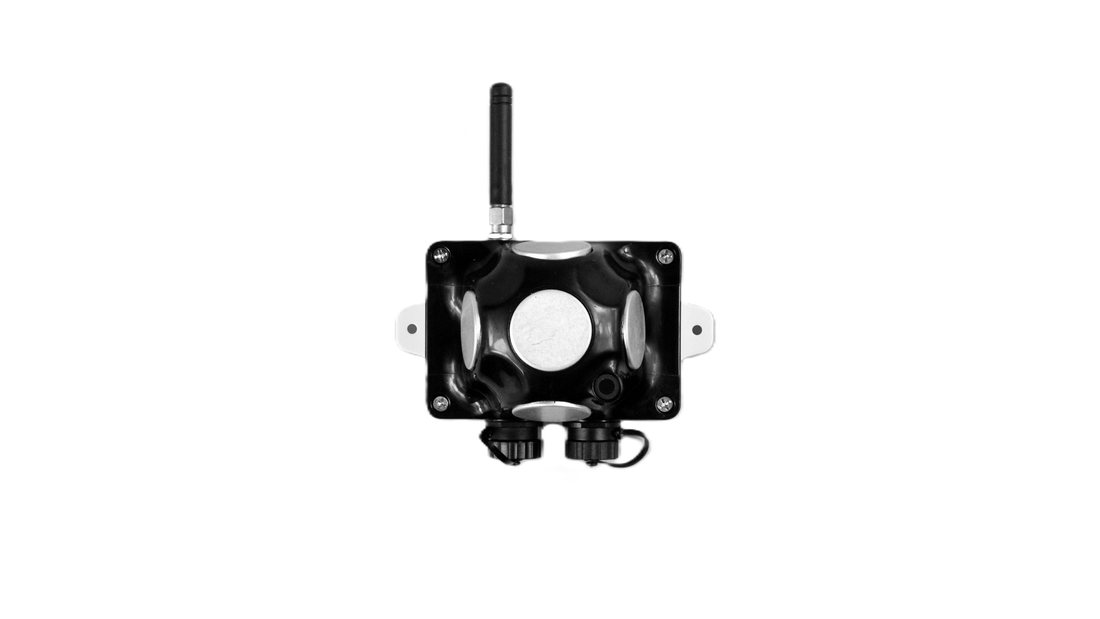
- TX1
- TX2
- TX3
- TX4
- TX5
Different Types of External Microphones
 This modification of the Super-Beacon allows you to place the receiving microphone anywhere on your robot or clothing. As a result, the microphone body itself will not interfere and will not be visible. It allows you to implement more accurately.
It is possible to connect External Microphone-IP67, Omni-Microphone-IP67, and Horn
It is also possible to use 2 External Microphones to calculate direction or to increase the reception area.
The Omni-Microphone-IP67 has a 1m wire length and connects to a 4×4 pinout in the default configuration.
The external microphone’s length is 25 cm (default), but it may be expanded up to 1m (optional).
 Be careful: You should have soldering skills to solder External Microphone on board
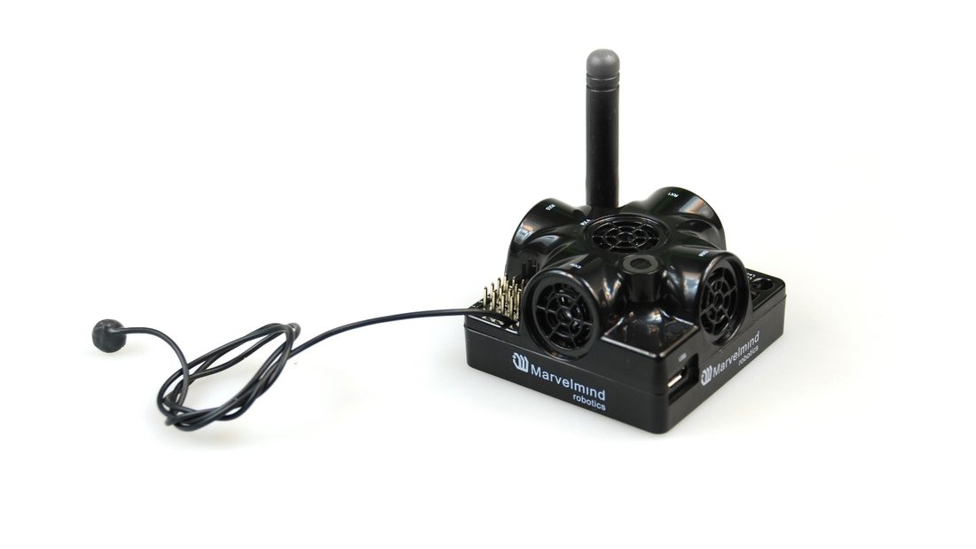
Figure 1: Super-Beacon with one External Microphone connected
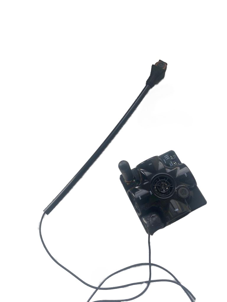
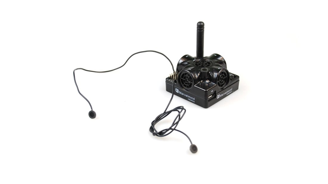
Figure 2: Super-Beacon with two External Microphones connected
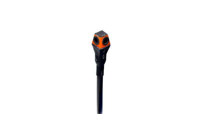 Figure 3: Super-Beacon with Omni-Microphone connected
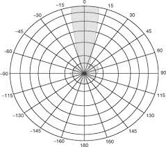
Figure 4: Receiving diagram (with Omni-Mic-IP67)
Omni-Microphone Schemes
 If you don’t want to use a 4×4 pinout to connect the Omni-Microphone, you can solder it using this scheme.
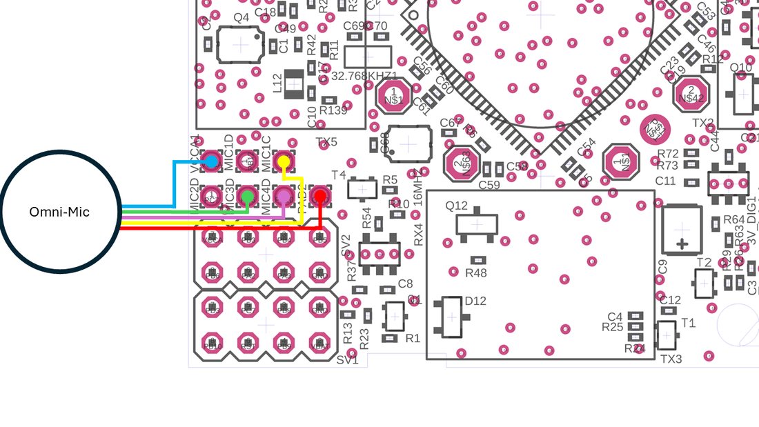 Be careful: You should have soldering skills to solder the Omni-Microphone on the board.
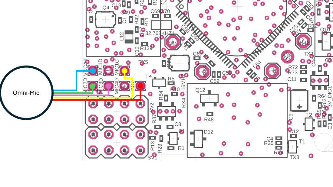 Figure 4: Omni-Microphone connection for Super-Beacon
Figure 5: Omni-Microphone connection for Super-Beacon-2, 3, 4
External Microphones Schemes:
 There can be some beacons (from one of the batches) with mixed default microphone wires’ colors.
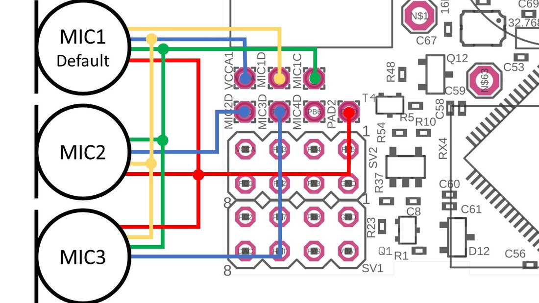
Figure 6: Connection for the beacon with switched blue and yellow wires
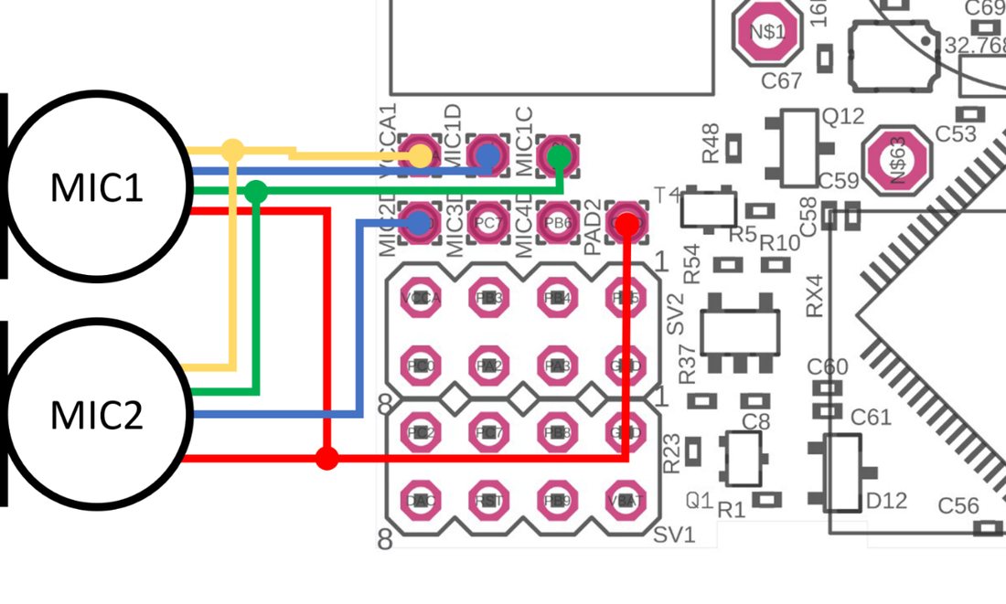
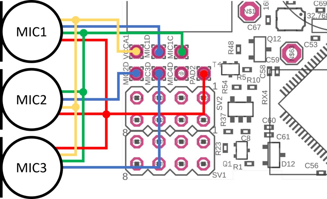 Figure 7: One External Microphone connection
Figure 8: Two External Microphone connections
- Option 1: Settings for reception from 3 microphones in parallel: RX1 – integrated microphone, RX2, RX3 – soldered microphones:
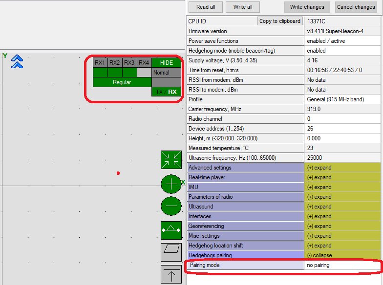
- Settings to enable internal and two external microphones to work together.
- Option 2: Settings for paired microphones to calculate direction: RX2 – left microphone, RX3 – right microphone:
External Microphone Extension for Mini-RX
This modification of the Mini-RX beacon allows you to place the receiving microphone anywhere on the robot or on clothing. As a result, the microphone body itself will not interfere and will not be visible. It allows you to implement more accurately.
It is also possible to use 2 external microphones to calculate the direction or to improve and increase the reception area.
 The length is 25 cm (default) and may be expanded to 1m (optional).
At maximum, Mini-RX supports up to four microphones: either 3 + 1 including the internal one or 4 external microphones, if the internal one is unsoldered. Such a configuration – with four external microphones – is used, for example, in the Marvelmind Jacket.
 Be careful: You should have soldering skills to solder External Microphone on board.
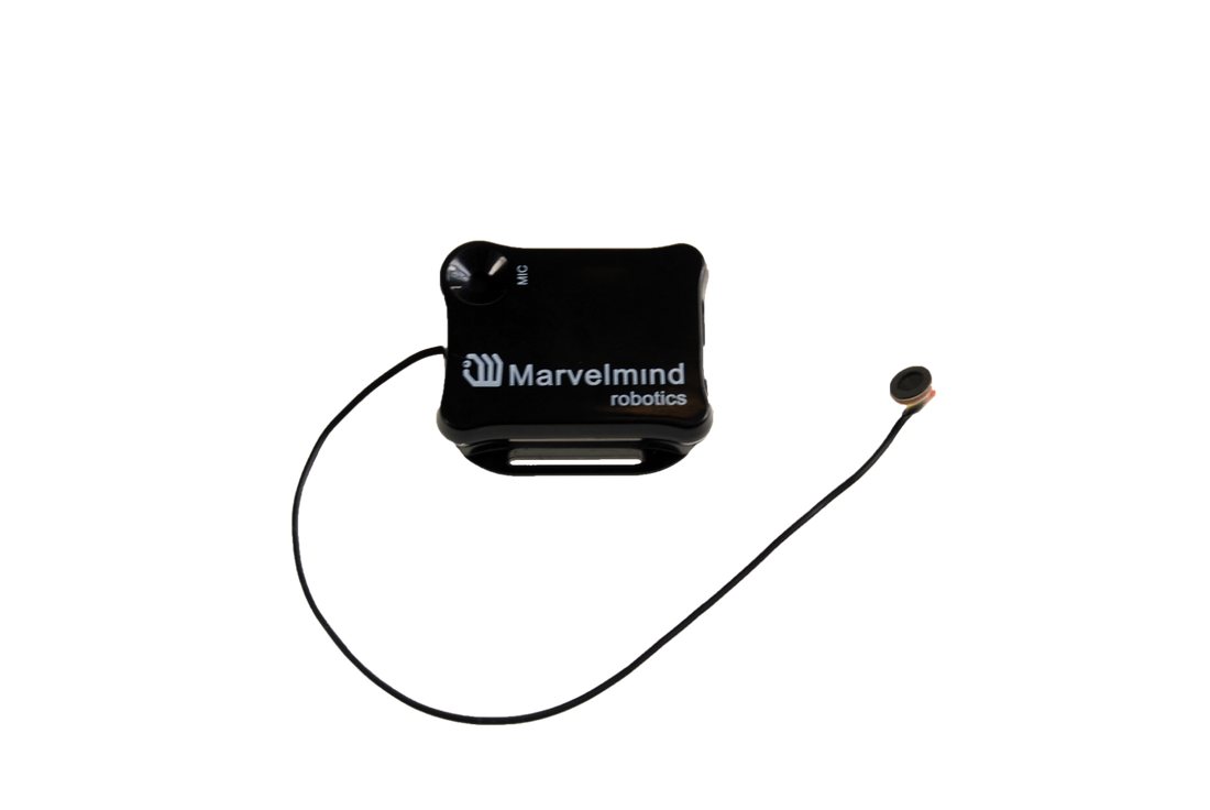
Mini-RX beacon
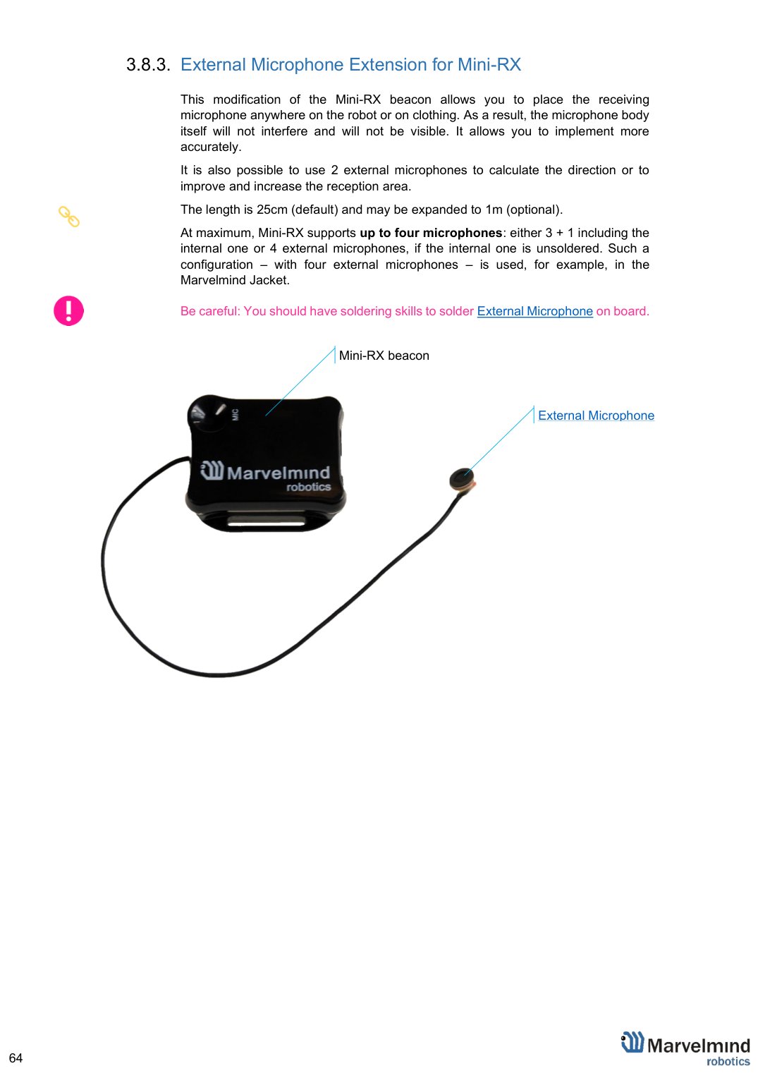
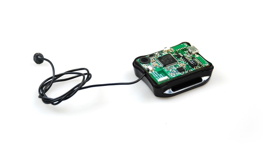
Figure 1: One External Microphone with housing
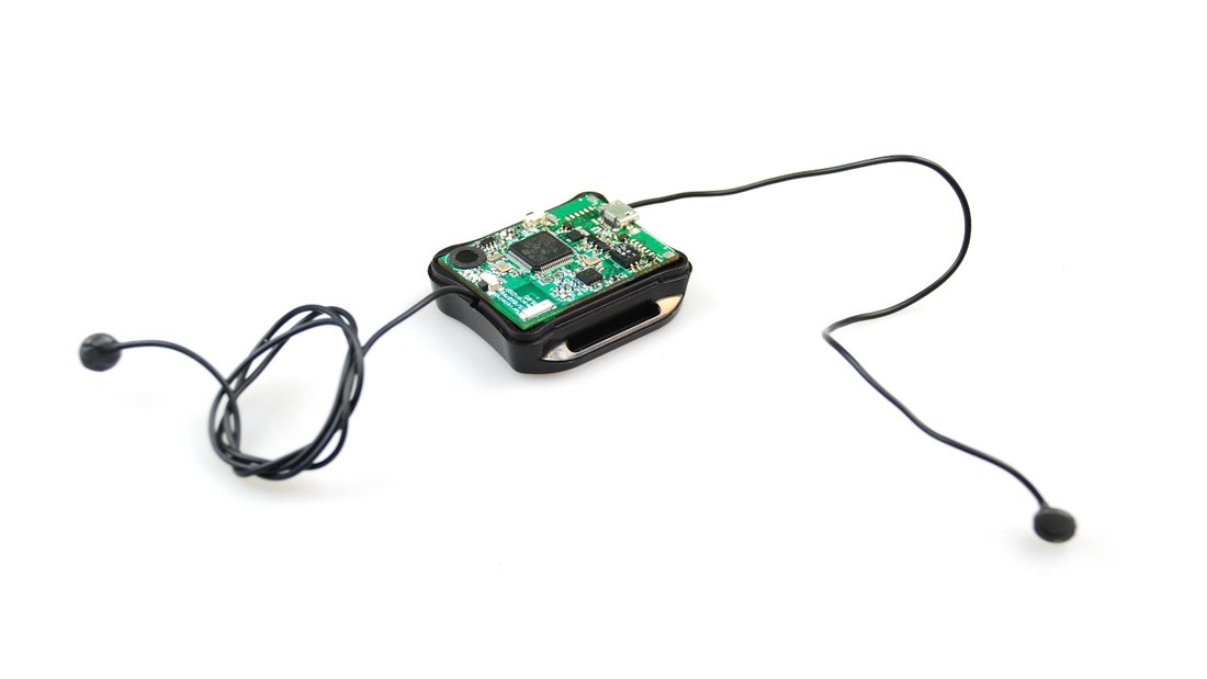
Figure 2: Two External Microphones with housing
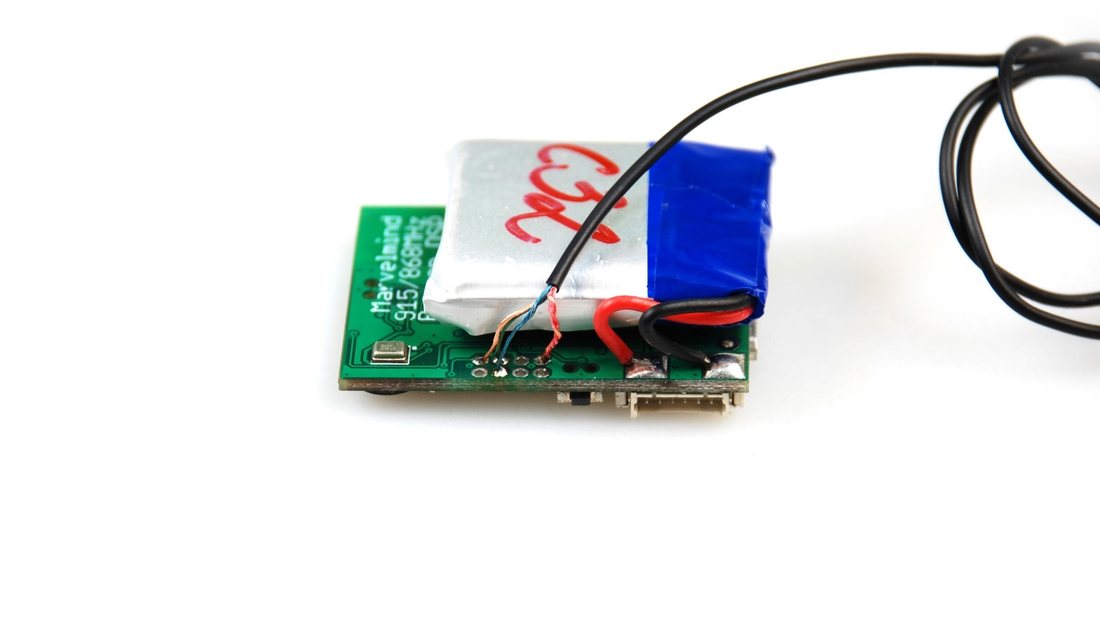
Figure 3: One External Micropohne soldering
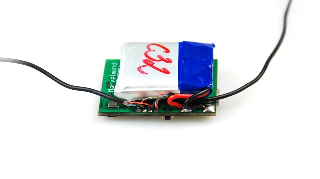
Figure 4: Two External Microphones soldering
External Microphones Schemes:
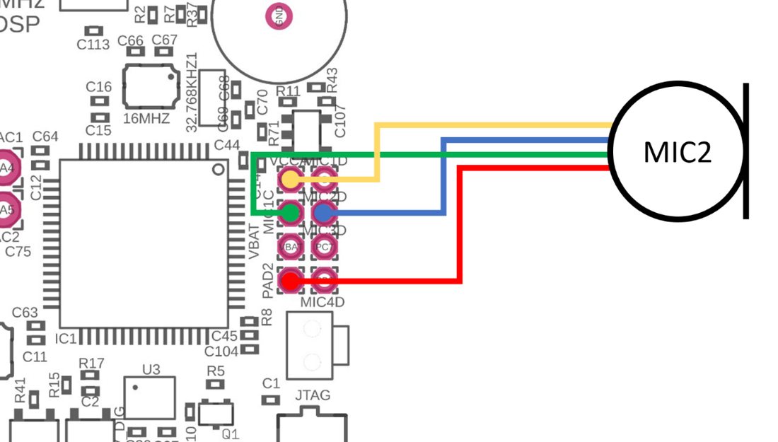
Figure 5: One External Microphone connection
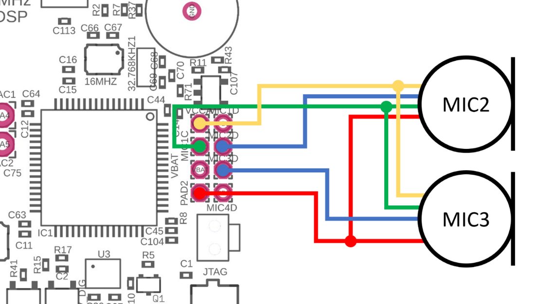
Figure 6: Two External Microphones connection
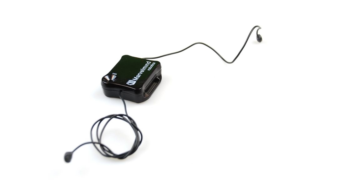
Figure 7: Two External Microphones final view
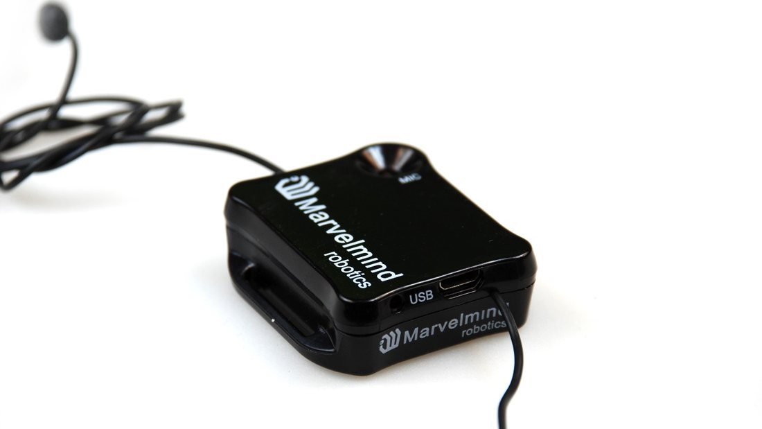
Figure 8: Two External Microphones Final View
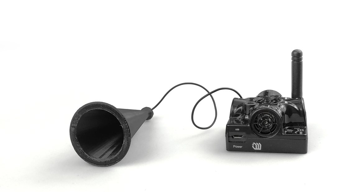
Horn
Horns are usually used for 1D tracking because they can detect ultrasound at an angle of ~10 degrees, but only at very large distances, ~100-150 meters.
For more information, check our help pages:
- Demo Video
- 1D Distance Measurements for Construction Sites Video
- Settings to enable both Horn and internal microphone:
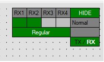
- Settings to enable both Horn and internal microphone
- Settings to enable Horn only:
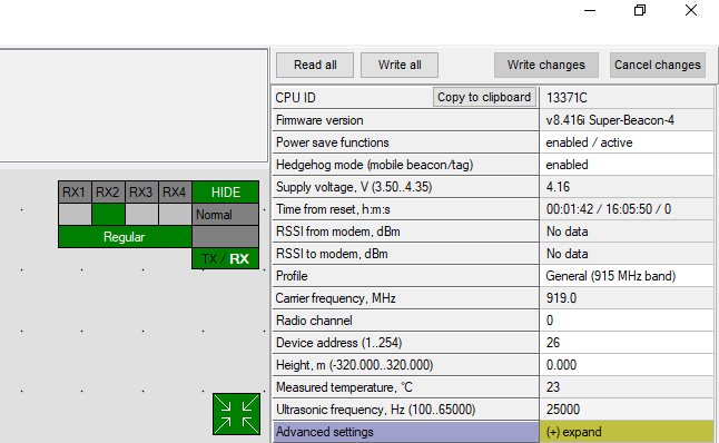
- Settings to enable Horn