
Indoor Positioning system for Autonomous Mobile Robots
With ±2cm Accuracy in GNSS-Denied Areas
Autonomous mobile robots (AMRs) and AGVs require indoor positioning that GPS cannot provide because it doesn’t work indoors.
Marvelmind ultrasound RTLS delivers ±2cm accuracy – 10x more accurate than UWB (10-30cm) and 100x more accurate than Bluetooth. The system outputs XYZ coordinates, IMU and other data via USB, UART, or CAN, with native ROS and ROS2 drivers for immediate integration into any robot navigation stack. Native GPS protocol – NMEA0183 – is supported out of the box as well.
It is a great alternative for robot’s positioning and navigation when LIDAR or optical positioning system struggle techically or simply to expensive.
Very quick hints for our customers
If you are building a robot or an AGV and have to very quickly decide what to choose as a positioning and navigation system, choose the following:
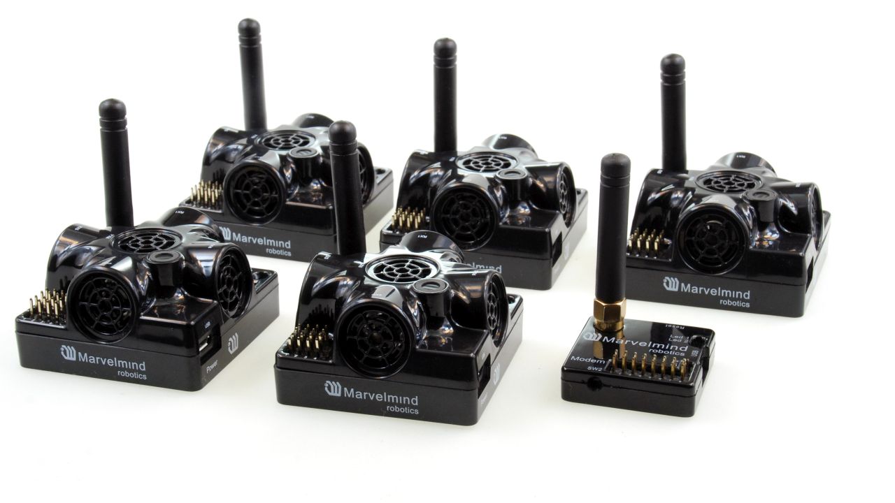
- Starter Set Super-MP-3D – the simplest and the most versatile set to start with
- Starter Set Super-MP-3D + Super-Beacon – if you want Location+Direction
- Starter Set Super-MP-3D + Super-Beacon + 2 x Omni-Microphones – if your area is larger than 20x20m of open space or your stationary beacons are 30 degrees from the horizon or lower. You will be able to build robots with this kind of driving capabilities. Our robot Boxie is using this configuration since it is the most advanced and flexible one
But what if you need to cover a large warehouse or a plant (10,000-100,000m2) with a dozen of robots? Can this be done? – easily! Just more submaps with more stationary beacons for more coverage and more mobile beacons to track more mobile objects. More about submaps you can find on the Downloads page.
Using Marvelmind Indoor "GPS" for robots, vehicles, and AGVs
Marvelmind indoor positioning system (Marvelmind IPS), also known as Marvelmind Indoor “GPS” or Marvelmind RTLS, is widely used for different types of autonomous robots, autonomous vehicles, AGVs, and forklifts for various purposes:
- Autonomous navigation and positioning for robots indoors and outdoors
- Tracking AGVs, vehicles, or forklifts
- Providing geo-fencing for robots, forklifts, and people
- General robotics research and development
- Robotics education and competitions
- Swarm robotics
One of the major tasks for autonomous robots and drones is automated scanning and inspection – a very important but repetitive task with a predictable routine that requires constant attention and accuracy.
It is what machines can do very well, but humans are prone to tiredness and errors.
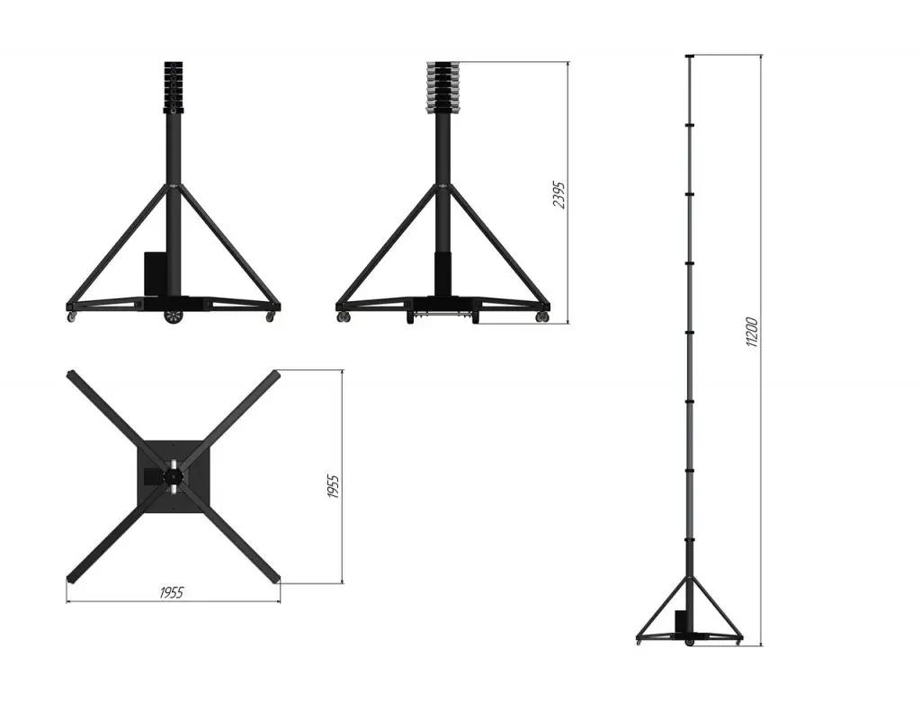
Of course, drones for warehouse indoor scanning look like a fancier solution, and we discuss it with our customers and potential customers on a weekly basis. However, if you want something practical that reliably works and can be used for very real applications today – not for research and innovation – then robots for scanning shall be your choice today.
Use Cases
Who Uses Indoor GPS for Autonomous Robots - and For What
Autonomous mobile robots require centimeter-level indoor positioning that GNSS cannot provide indoors. Marvelmind ultrasound RTLS is used across three major application areas: robot-assisted inspection in warehouses and factories, research and university robotics labs, and AMR/AGV navigation in industrial facilities. Below are the most common real-world deployment scenarios.
Robot-Assisted Inspection and Automated Scanning
Autonomous robot scanners require a reliable indoor positioning system to follow precise, repeatable routes through warehouse aisles, factory floors, or greenhouses. Manual scanning with handheld barcode readers, QR scanners, or RFID equipment is slow, error-prone, and expensive at scale. A robot equipped with Marvelmind Indoor GPS replaces the human walk - scanning the same route daily, hourly, or on schedule, with ±2cm positional accuracy that ensures every label, code, or RFID tag falls within the scanner's read range.
Our automated scanning and inspection solution is built around the Boxie Scanner robot - a compact autonomous platform that carries any scanning payload: cameras, barcode readers, QR scanners, or RFID readers. The robot navigates independently, supplies power to the payload from its own battery, and logs the position of every scan with ±2cm accuracy. The system integrates with WMS and ERP via open API.
Key facts for robot scanner deployments:
- ±2cm position accuracy - sufficient for barcode, QR, and RFID reading at predictable distance
- 2D tracking only required - lower cost and complexity than drone-based scanning
- Robot works 8, 12, or 16 hours between charges - no pilot needed, no crash risk
- Multiple robots can operate simultaneously in one space - each tracked independently
- Coordinates are georeferenced - every scan is recorded with exact XYZ position and timestamp
Applicable environments: warehouses, logistics centers, factories, assembly plants, greenhouses, airport cargo terminals.
Learn more about automated scanning and inspection solutions →
Autonomous Indoor Navigation for Research and Universities
Universities, PhD students, post-docs, and research labs are among the most active users of the Marvelmind indoor positioning system. The combination of ±2cm accuracy, open API, ROS/ROS2 native drivers, and transparent pricing makes the system well-suited for robotics research that demands ground-truth positioning without the cost and complexity of optical tracking systems.
The system has been used at universities worldwide for autonomous robot navigation, swarm robotics, drone autopilot research, autonomous vehicle drift control, indoor archaeology, and people tracking research. An independent published comparison of indoor positioning systems concluded that Marvelmind IPS delivers accuracy competitive with optical systems at a fraction of the cost, and significantly outperforms UWB-based alternatives. See the full list of university cases and published research papers.
Why research teams choose Marvelmind over alternatives:
- ~10x more accurate than UWB (±2cm vs. 10-30cm), ~100x more accurate than BLE
- No cloud required - all positioning calculated on-premise, no data leaves the lab
- Full ROS and ROS2 support with published drivers and code examples
- Compatible with TurtleBot, custom AMRs, drones, PixHawk, ArduPilot, Jetson, Arduino
- Open interfaces: USB, UART, SPI, CAN, I2C - integrates with any research platform
- Customizable hardware, protocols, and software - the team works directly with end users
- Same-day or next-business-day shipping - no waiting weeks for research hardware
Notable published research using Marvelmind: autonomous drift cornering at UC Berkeley, ROS sensor fusion at multiple universities, Drone Referee (MSD 2017/18), indoor archaeology positioning at Israeli excavation sites, cow activity tracking indoors, anti-COVID spray distribution robot.
See the full university solutions page and research examples →
AMR and AGV Navigation in Warehouses and Factories
Autonomous mobile robots (AMRs) and automated guided vehicles (AGVs) in industrial facilities require precise, scalable, and infrastructure-stable indoor positioning. Unlike systems based on QR codes on the floor (easily damaged or blocked), SLAM (computationally complex and accumulates drift), or UWB (10-30cm accuracy, insufficient for tight aisle navigation), ultrasound RTLS provides absolute ±2cm XYZ positioning that does not drift, does not depend on lighting, and scales from a single robot to 250 simultaneous vehicles.
Marvelmind has deployed tracking systems for industrial customers including a 450×450m T-shaped warehouse with 120+ forklifts tracked simultaneously using 123 stationary Super-Beacons. The system streamed real-time XYZ coordinates to the customer's analytics platform via UDP and open API, enabling automatic job allocation based on each vehicle's current location. A second deployment tracked 10 forklifts across 14 stationary beacons. Both systems were deployed remotely by Marvelmind. See the full case studies.
Key advantages for AMR and AGV deployments:
- Coverage from a single 1000 m² submap to unlimited multi-building areas via networked submaps
- Up to 250 mobile robots tracked simultaneously with individual ±2cm accuracy
- No floor modifications - beacons mount on walls or ceiling at 3-4m height
- Output via USB, UART, SPI, CAN, or UDP - integrates into any existing fleet management system
- Accuracy is independent of robot speed or update rate - see the technical explanation
- Works in dusty, temperature-variable, and electrically noisy industrial environments
Applicable tasks: autonomous delivery, inter-zone transport, picking assistance, automated inventory counting, safety zone enforcement, multi-robot coordination.
What Marvelmind starter set to choose?
If you don’t have time to study the detail but need to choose fast and safe, choose Starter Set Super-MP:
- MP stands for Multi-Purpose. The set indeed supports multiple architectures and multiple configurations, thus giving the highest flexibility:
- 2D tracking with up to 2 submaps
- 2D tracking with up to 3 mobile beacons (robots)
- 2D tracking with Location+Direction
- 1D tracking with up to 4 mobile beacons
- Starter Set Super-MP supports different architectures: NIA, IA, and MF NIA
- The beacons have a 900-1000 mAh LiPol battery inside, which allows for easily and quickly deploy the system without an external power supply
- Beacons have external antennas – more robust radio connectivity with the modem
- Super-Beacons can receive and transmit ultrasound. Thus, they can work as stationary and as mobile beacons
- Super-Beacons have DSP (digital signal processor) inside. Thus, it can receive several ultrasound channels at once and work in IA
- Super-Beacons have IMU (3D gyro + 3D accelerometer)
Remember that one mobile beacon per robot gives you only one location. For location and direction, you need the Paired Beacons configuration – two mobile beacons per robot. See the following variant.
For Location+Direction, you need more than one mobile beacon per robot. Thus, the easiest is to add to the Starter Set Super-MP an additional Super-Beacon.
Examples of precise indoor positioning and navigation for robots
Autonomous Delivery Robot - car assembly plant demo
Marvelmind Autonomous Delivery Robot v100.
IA with 15 stationary beacons and one modem for Indoor “GPS” coverage. See more: https://youtu.be/TWWg_8JHYzo.
The same Indoor “GPS” map supports on top of the robot shown in the video:
- Multiple mobile robots and forklifts tracking as well as people tracking. Altogether – up to 250 beacons/objects – stationary+mobile combined
Robot v100 example with detailed explanations
This is the same demo as https://youtu.be/TWWg_8JHYzo, but with additional verbal comments explaining what is on the video and in the system in general.
Configuration:
- Marvelmind Autonomous Delivery Robot: https://youtu.be/efOc-ItVvgg
- IA with 15 stationary beacons and one modem for Indoor “GPS” coverage.
Robot’s specs:
- Fully autonomous delivery between any points covered by Marvelmind Indoor “GPS”
- Up to 100kg payload
- Driving time more than 16h on a single charge: https://youtu.be/JaxRd_9D1fQ with 60+kg payload
- Automatic obstacle avoidance and detection
- The delivery route can be reconfigured by one button click in 1 second
- Charging time is less than four h. So, 2-shift work (16h) and one shift (8h) charging is supported
- Re-configurable capacity: 1 large box of up to 65x65x160cm to up to 8 boxes of 65x65x15cm – one shelf vs. multiple shelves
- The same Indoor “GPS” map supports:
- Multiple mobile robots and forklifts tracking and people tracking. Altogether – up to 250 beacons/objects – stationary+mobile combined.
- Mobile beacons in the Paired Beacons configuration for Location + Direction in IA modem with two external Omni-Microphones can be seen installed on the robot
- Stationary beacons in 2D tracking are installed on the walls
Robot driving fully autonomously using Marvelmind Indoor "GPS"
A fully autonomous robot is driving on its own, relying on:
- Marvelmind Indoor “GPS”
- On-board odometry and inertial units (IMU)
The robot receives coordinates for the key points to visit from the user (table on the right) and then creates and follows the path by constantly correcting its position against the path. Coordinates are formed automatically in the Dashboard by simply clicking on the map.
Distances between beacons are up to 36 meters. It is possible to cover the entire campus with precise “GPS” by installing more beacons every 20-30 meters.
Fully autonomous small delivery robot moving in office environment
- A mobile beacon is installed on the robot
- Stationary beacons are installed on the walls
- Blue dots – location of the robot (mobile beacon) measured by the Marvelmind Indoor Navigation System
- Yellow dots – location of the robot obtained from its own inertial/odometry system
- Big green dots – stationary beacons installed on the walls
Fully autonomous robot driving demo: "8-loop" track
Marvelmind Indoor Navigation System + autonomous robot Marvelmind Hermes demo:
- “8-loop” (7x2m) track
- Fully autonomous driving The Marvelmind Indoor Navigation System Starter Set deployed in an 80m2 room
A mobile beacon is attached to the top of the robot. The robot receives its coordinates with ±2cm precision from the Marvelmind IPS and uses them to drive through the track autonomously.
There are intentional mild shadows for the Indoor Navigation System (column, padded stools), imitating real-life environments. While in the shadows, the robot relies on its inertial navigation system and odometer.
Domino robot with positioning and direction based on Marvelmind Indoor "GPS"
Marvelmind Indoor Navigation System has been used by an ingenious domino placing robot. The system was used for precise location and direction – see the mobile beacons placed on the base to achieve the best directional accuracy.
See the original video as well: World Record Domino Robot (100k dominoes in 24hrs)
Robotics solutions
Localization
One of the biggest problems for any autonomous robot is to answer the question: “where am I?”. The question immediately explodes into subsets of questions:
- Where am I against my expected location at the moment?
- Where am I against my next waypoint?
- Where am I against the other object: robots, people, obstacles, charging stations, etc.?
But everything starts with localization against some reference; for example, (0,0,0) coordinates, whatever could be or against the starting point or similar. Many other questions are derivatives of that master question.
Localization against what?
There are several primary options:
- Against myself – the center of the robot, for example
- Against an external reference point
Against myself is more straightforward in many cases, but it is about obstacle detection and avoidance rather than moving and navigating in space. Let’s discuss in detail positioning and navigation against external references.
See more about coordinate systems:
Why not SLAM?
SLAM (Simultaneous localization and mapping) is a terrific method. But it may impractical in some industrial applications, where the environment is changing, poorly structured or unpredictable: warehouses, assembly plants, and intra-logistics in general:
- Often, it is simply more efficient to split the task into two stages: 1) Mapping, 2) Localization
- Obstacle detection and avoidance are not about mapping and localization at all. It is a point 3). It is just a different task and must be solved differently. LIDARs are well-suited for obstacle detection, but they are not particularly good for mapping, if the environment is changing – the can do too many mistakes
- The same limitation mentioned about LIDARs applied to visual SLAM systems – they may be confused, and they have to rely on other methods for the rectify the mistakes
- In general, sensor fusion is the best approach and gives the best result and is recommended when commercially and technically viable
Localization inside-out, inside-in or mix?
If the robot carries all required for localization on board, it is inside-out localization. Humans and animals use inside-out localization. They do generally not need direct and constant information about where they are in terms of a continuous stream of coordinates. They determine it “inside” based on different outside clues.
Some people call the process visual odometry. Of course, it works much better with a regular wheel (feet) based odometry, if the floor and the environment is suitable for that. And this is why it is sometimes easier to make a robot with a navigation system than just a navigation system for any robot. Developers of such “universal positioning systems” may struggle because the data from an odometer could be in virtually any format – analog with different values or digitally coded with an unknown format. It could be with absolutely different resolutions, and many other parameters could be different.
Thus, most systems inside robots are inherently linked. It shall be understood and considered by anyone designing a robot right from the beginning.
Our indoor positioning system uses the outside-in localization: the mobile robot can be relatively stupid or even not aware that it is being tracked. The outside system tracks it or, in our case, trackes a mobile beacon (tag) attached to the robot. If the robot is smart, it is using its data and drives autonomously around based on its XYZ coordinates and waypoints. If it is not smart, it can be remotely controlled. Still it will be controlled by the system – not by humans – so, it will remain fully autonomous but it is intelligence, at least, the one that is responsible for positioning, navigation, and autonomous drive is outside of its moving body.
The benefits of the outside-in architecture:
- You can track “dumb” mobile objects like forklifts or very simple robots, for example, based on RC cars
- You can track “unconnectable” mobile objects, for example, humans and improve safety drastically, when robots are around. Robots don’t have to detect the humans. They know where the humans or other moving objects, including other robots, are
- The robots become far less expensive
Recommendations on selection:
- If you have 1-2 robots driving around a very large but structured and “predictable” warehouse, the inside-out localization can be financially more beneficial. Yes, each robot is more expensive but you don’t need the infra-structure in the warehouse
- If you have multiple robots in the same warehouse, it is more and more beneficial to use the outside-in localization, because the robots become substantially less expensive
- If you have unstructured environment and the inside-out localization struggles, uses the inside-in approach without hesitation
- In the most complex conditions, the sensor fusion approach and all sorts of hybrid solutions, typically, bring the best results
- Particularly good the outside-in approach for swarm robotics
Choosing a reference point
In the case of GPS, the coordinates are available in regular latitude and longitude of the Earth. In some cases, it may be helpful when, for example, the robot moves out of the indoors. But for the majority of the real indoor cases, we are interested in local coordinates only.
Thus, we are choosing them at our convenience. In Marvelmind Indoor “GPS”, usually, the system assigns one of the stationary beacons as (0,0,0) or (o,0). But you can set any point on the map as (0,0):
Moreover, geo-referencing is possible, assigning external GPS coordinates to the internal (0,0,0) point. After that, the stream of coordinates from the Marvelmind Indoor “GPS” would be in absolute GPS coordinates in NMEA0183 format. Or in the internal format. See more on the open protocols.
Direction
Unlike outdoors, where a magnetometer/compass is available, calculating indoor direction, is not a trivial task. Particularly, it is difficult in static.
For example, your robot can easily have a precise location using our system. But if your robot doesn’t know its current direction – where it is facing – it isn’t easy to decide where to drive.
It is possible to rather quickly calculate the robot’s direction by measuring its current location point, driving 1m or so straightforward – keeping the straight direction using IMU/gyro – then measuring a new location, and by knowing two points and knowing that it was a line – not a curve – to calculate the robot’s current direction. Later, during driving, employ the same technique all the time. See an article: How many mobile beacons do I need per drone? – it is less critical for robots, because they are less size- and weight-limited. Still, it is very applicable to robots as well.
These older robots are using the approach:
The method is simple and requires only one mobile beacon (tag), but it works only if you can drive. You often can’t go and need to localize right on the spot – in static. What to do?
The paired beacons
Our recommended way to get direction in static is to use a Paired Beacons configuration.
Here is more about it. In NIA:
Another example is a self-driving autonomous Robot v100 with a base between the mobile beacons ~60cm. In IA:
Similar configuration with external microphones on a single mobile beacon. Though it was done for VR, it could easily be a robot. The base between the microphone is ~20cm. In IA:
There are many alternatives for each solution. For example, motion capture with external cameras. Is it a precise and suitable solution for both location and direction? – sure! Yes! Is it practical for industrial robotics? – not really:
- Costly. Very costly, at least, when this article was originally written (2021)
- It is not tuned to a harsh environment of factories or warehouses
- Prone to multiple limitations: too little light, too intense light, fog, temperature changes, power supply, etc
Thus, we are not touching all possible localization options here. Only what is relatively relevant and implementable.
Obstacle detection and avoidance
Obstacle detection and avoidance is a separate task from localization
As discussed above, the SLAM approach promises obstacle detection, mapping, and localization at the same time. It sounds like a dream, but the reality is harsher and less friendly.
In real-life conditions of poor lighting, a lot of high-dynamic range light sources – bright sun through windows together with very dark shadows of a warehouse, different other sources of light from headlights to all sorts of scanners, the visual-based SLAM solutions can be very easily confused to the point of a complete loss of localization. Additional methods for correcting major mistakes are required when SLAM systems can’t choose between different options correctly. Sensor fusion is the solution.
Additionally, why optimally (technically and economically) solve the task of localization, it is more difficult to optimally solve the task of obstacle detection, simply because the tasks and requirements are different in nature.
But the SLAM approach unnecessarily complicates the task by loading obstacle detection on top of mapping and localization:
- Mapping
- Localization
- Obstacle detection
All three elements are crucially important for autonomous driving, but they are not required to be the same thing. They are not required to be done with the same methods and by the same sensors.
Integrated robots vs. Split robots approaches
One of the important points is to clearly distinguish between the robots and their payloads. It is very much like rockets and satellites. Two things are different and shouldn’t be mixed up. The same story with tractors and tractor mounted equipment.
We produce “rockets” and “tractors”:
You install your payload on them from basic baskets to arms and complex scanners. You can control them as well via our open interfaces and protocols.
Integrated robots approach
Very often, the robots are fully integrated, i.e., their payloads are merged together tightly. There are pros and cons to the united robotics approach.
Pros:
- It can be easier to build because the robot is tuned for one task only. Very focused
- Simpler to operate
- It may be lighter
- It may be more robust
- It may be less expensive in the short run
Cons:
- Inflexible. And that is a big thing. You, theoretically, have a very capable robot, but is tuned only for one thing but you need another
- It can be more expensive in the long run due to inflexibility and a need for multiple different types of robots for different tasks, probably, even from different manufacturers
Split robots approach
Pros:
- Flexible in usage. With a limited number of robot platforms and a limited number of types of mounted equipment it is possible to virtually unlimited amount of different configurations
- Flexible in development, because parts can develop independently and only interfaces (electrical, mechanical, SW) shall remain compatible
- The robotic platform can be simple, even primitive and still very functional, because it is just a platform – “tractor” or “rocket” – without sophisticated “satellites”
- Less expensive per robot
Cons:
- More complex integration. The robot consists of two parts, at least: “tractor” and “equipment”
- May be less robust, because split approach has more different variants, i.e. more testing required, more parties involved, etc. Potential incompatibility of depends on different manufacturers: robots and payloads
Examples of robotic platforms and payload/equipment
Robotic platforms:
- Autonomous delivery platform. It is really like a tractor, but it can carry different things – different payloads or different equipment
- Drone itself
Payload or equipment:
- Arms, for example, to take a box and put on the robot
- The basket on the robot
- The camera on the robot or drone
- All kinds of meters (chemical, radiation, noise, etc.)
- Scanners (3D, bar/QR readers, 5G/6G, etc.)
- Fire-prevention equipment
Swarm robotics
Making a single robot drive autonomously is not a very easy task. But to make a swarm of robots is even more challenging.
What are the challenges?
- When there are too many moving objects around – other robots – it is more difficult for each robot to make decisions because the environment moves uncontrollably and in a predictable manner.
- If the robots have to stream out or receive separate streams from a central computer, there may not be enough radio bandwidth or bandwidth to serve them all.
- Since the robots are autonomous and independent, they may randomly request access to shared common communication channels. If they are, and the channel bandwidth is not 10-100 higher than the peak throughput required, the chances of collision are high. Thus, a special central controller or a mechanism to resolve the collisions is required. Both increase the complexity and bring other limitations.
- Robots obstruct each other’s view of other objects around. Robots sense neighbors, whereas something to position against – like external fixed references – is not really.
What are the solutions?
Marvelmind can help with the localization of robots in swarms, which is the starting and the most crucial point, because, if it is adequately solved, then many other difficulties of robot swarms simply don’t happen.
See swarm examples and solutions below.