
Setting up the system
This chapter as a clean, readable HTML page.
The “Setting up the system” chapter of the Operating Manual, reproduced as a real HTML page. Anything unclear? Open the original PDF of just this chapter (pages 99-124) (also pinned top-left). Hub: all chapters.
Introduction
Our system supports Non-Inverse Architecture, Inverse Architecture, and MF NIA. However, we strongly recommend starting from NIA in a 2D configuration (2 stationary beacons and 1 mobile beacon). Once you achieve perfect results in NIA, you can set up the system in IA.
 Check:
8 basic steps from unpacking to autonomous drive/flight
Step-by-step guide on how to build complex maps
 Detailed explanation of complex map building:
DIP Switch Positions
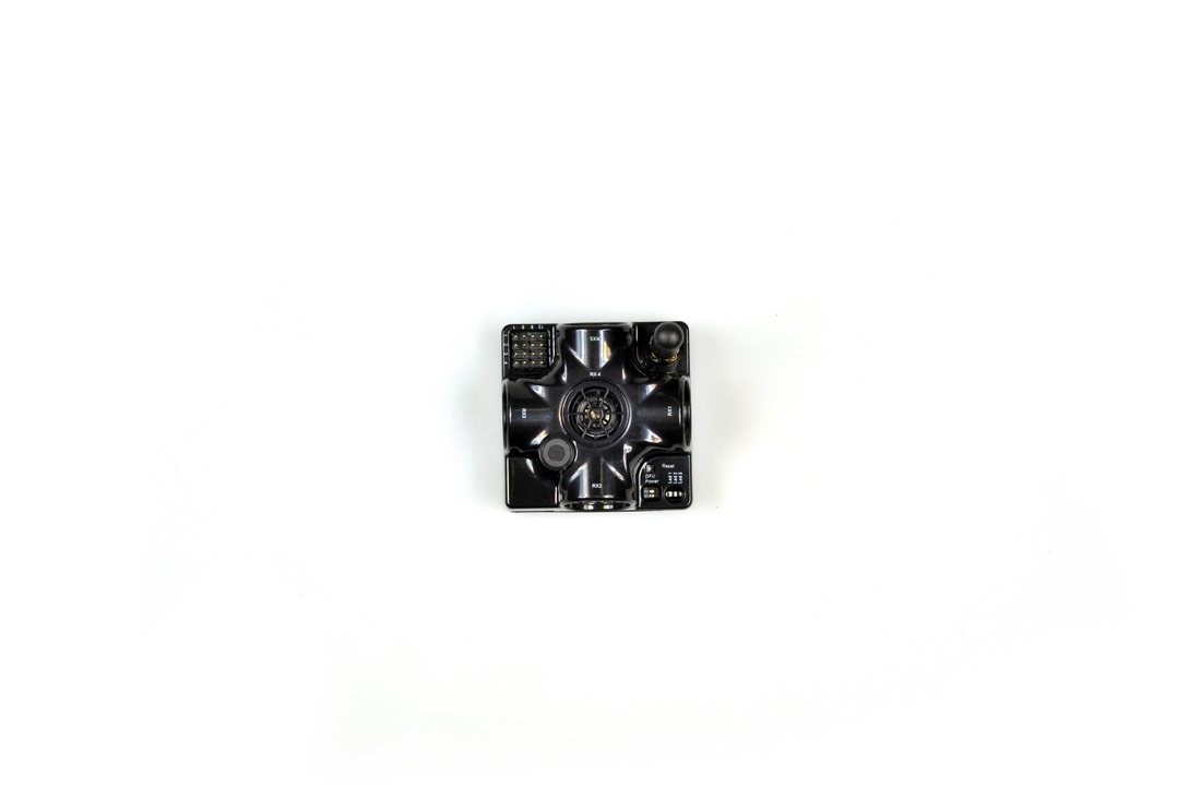
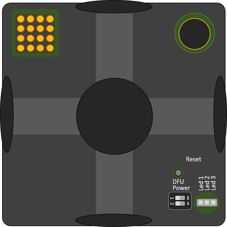
This chapter shows different DIP switcher positions of devices in the example of a Super-Beacon.
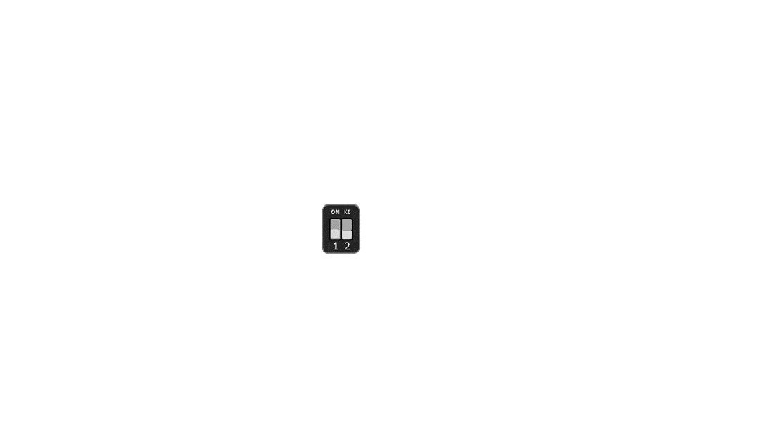
DIP Switch Position for OFF Beacon
Only charging the device is possible when the DIP switch is in this position.
Reset button
DIP switches
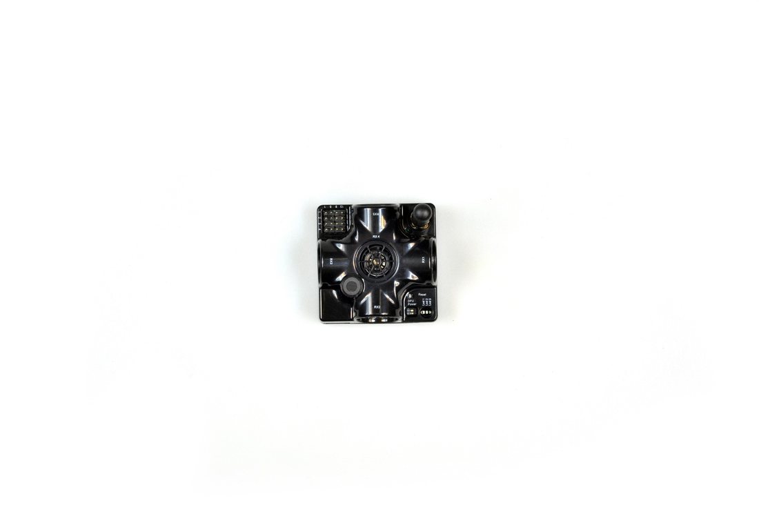
DIP Switch Position for Work and HEX Programming
Put DIP switch to this position:
To turn on the beacon
For HEX programming (via Dashboard)

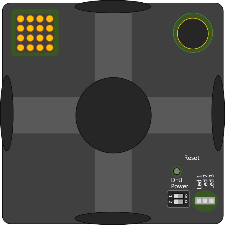
Reset button
DIP switches
DIP Switch Position for DFU Programming
 Put DIP switch to this position:
 For DFU programing (via Marvelmind DfuSe from the software package)

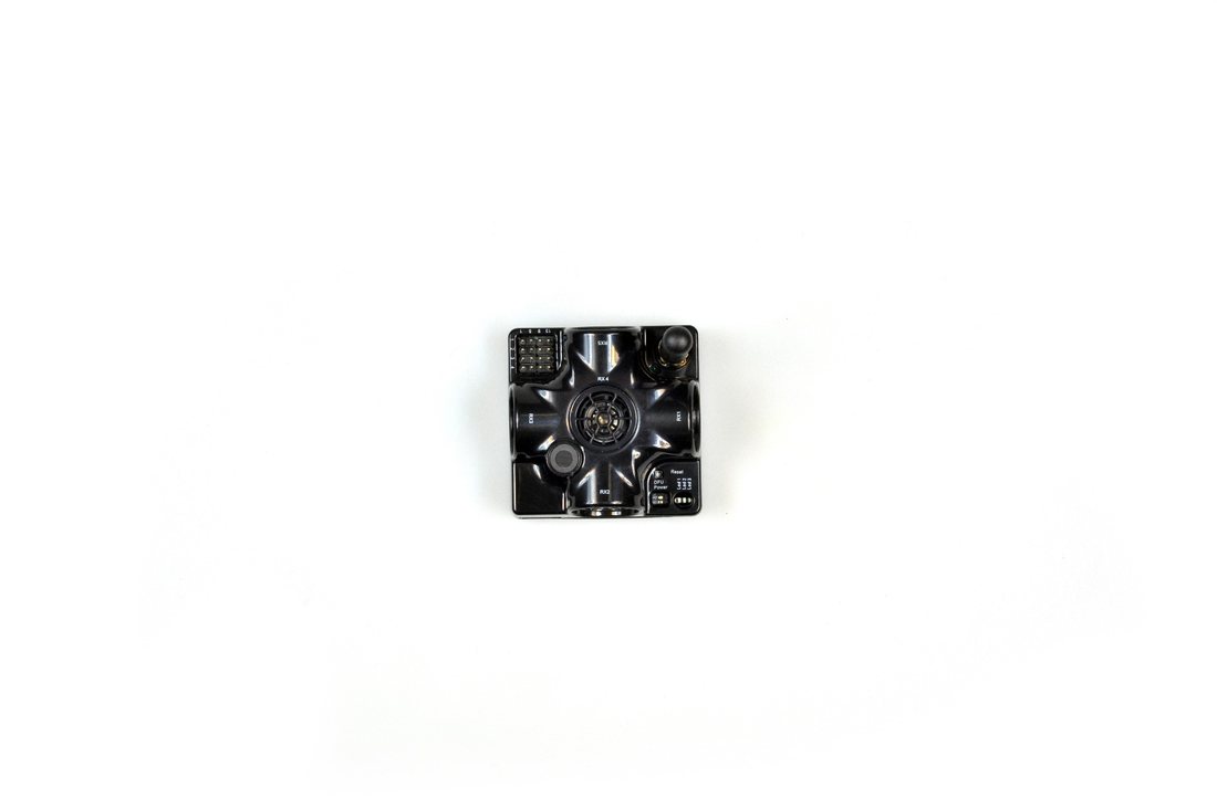
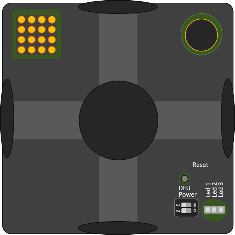
Reset button
DIP switches
Put the DIP switch in position for work and restart the beacon after DFU programming.
Starter Set Super-MP-3D (NIA, IA, and MF NIA)
 The steps below describe the first time you set up the system in NIA.
 Super-Beacons and Modem HW v5.1 required.
This Set can be used in IA and NIA. Use NIA Software for Non-Inverse Architecture and IA Software for Inverse Architecture.
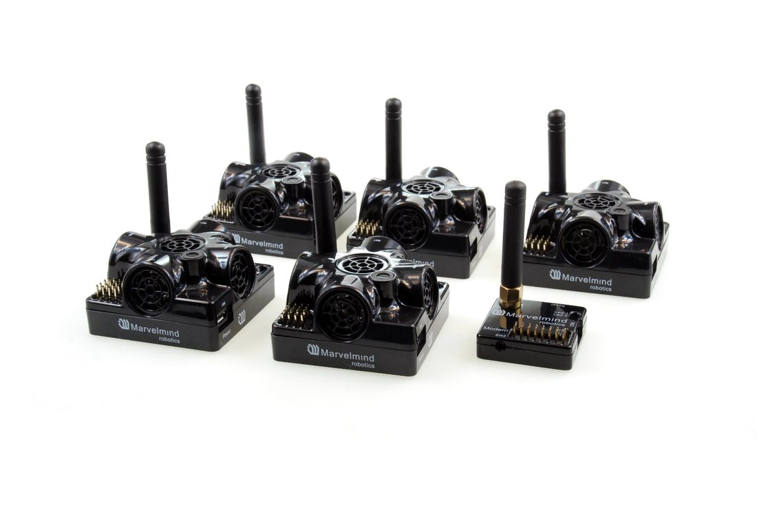

- Unpack the system. Check our tutorial video on Unpacking Starter Set Super-MP-3D
- Charge all the beacons using a USB cable. Complete charging takes about 1-2 hours
- Turn the beacons on: Place DIP switches as shown in the picture below

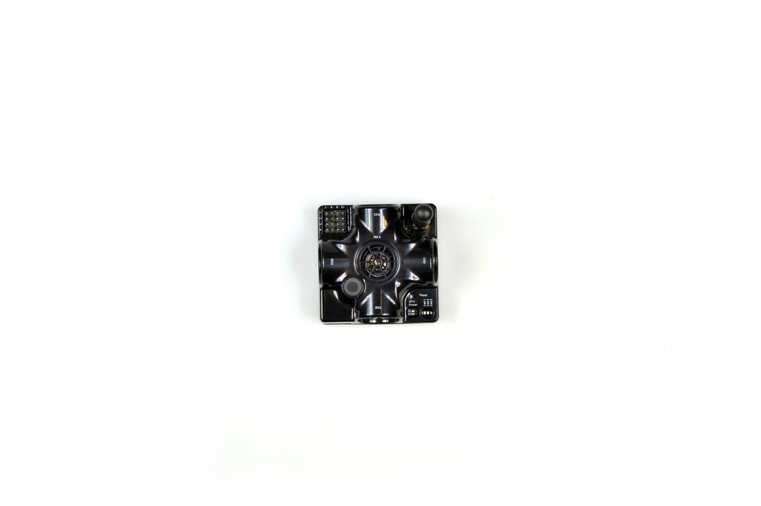
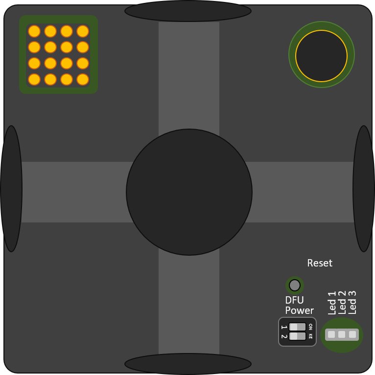
Reset button
DIP switches
- Download SW Pack
- Open Dashboard in NIA folder
- If you receive “Windows protected your PC” window, check this chapter
- Update all the beacons (HEX programming):
- Run the Dashboard and update the SW for all beacons and modem using Dashboard => Firmware => Choose the file => Program
- Note: On Windows 10 and later, the STM32 USB driver is installed automatically by the OS – no manual driver installation is required. The Dashboard does not show the driver download link in recent versions
- Ensure that:
- You are programming the modem’s SW to the modem and the beacon’s SW to the beacon
- You are using SW for Super-Beacon, if you have Super-Beacon, etc. You have the SW from the same SW pack, i.e., the Dashboard SW, modem SW, and beacon SW must be from the same SW pack. Don’t mix SW releases
 If you face difficulties in updating software for the devices, update them via DFU mode. Check out Software Updating via DFU Mode chapter
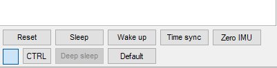
 While the beacon or modem is connected to the Dashboard, click the DEFAULT button to upload the default settings. Do this after each SW upgrade for all devices!

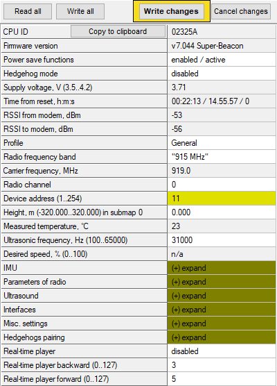
 Write down the beacon’s address for future use or change the address at your convenience. Enter the device address and press ENTER – press the Write changes button. Beacons’ addresses should not be repeated

 Place the stationary beacons high on the walls vertically in a way that will provide optimal ultrasonic coverage. Write down the beacon’s height for future changes in the settings. The help video on installation can be found here – Help: how to place beacons
 - Side view of 2D configuration:

 Place the stationary beacons high on the walls vertically in a way that will provide optimal ultrasonic coverage. Write down the beacon’s height for future changes in the settings. The help video on installation can be found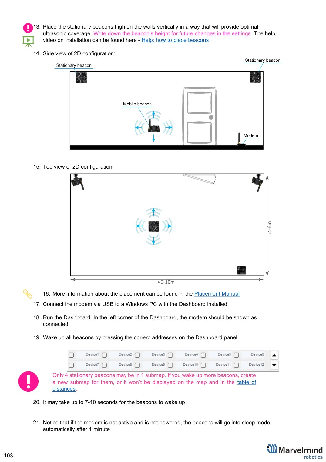
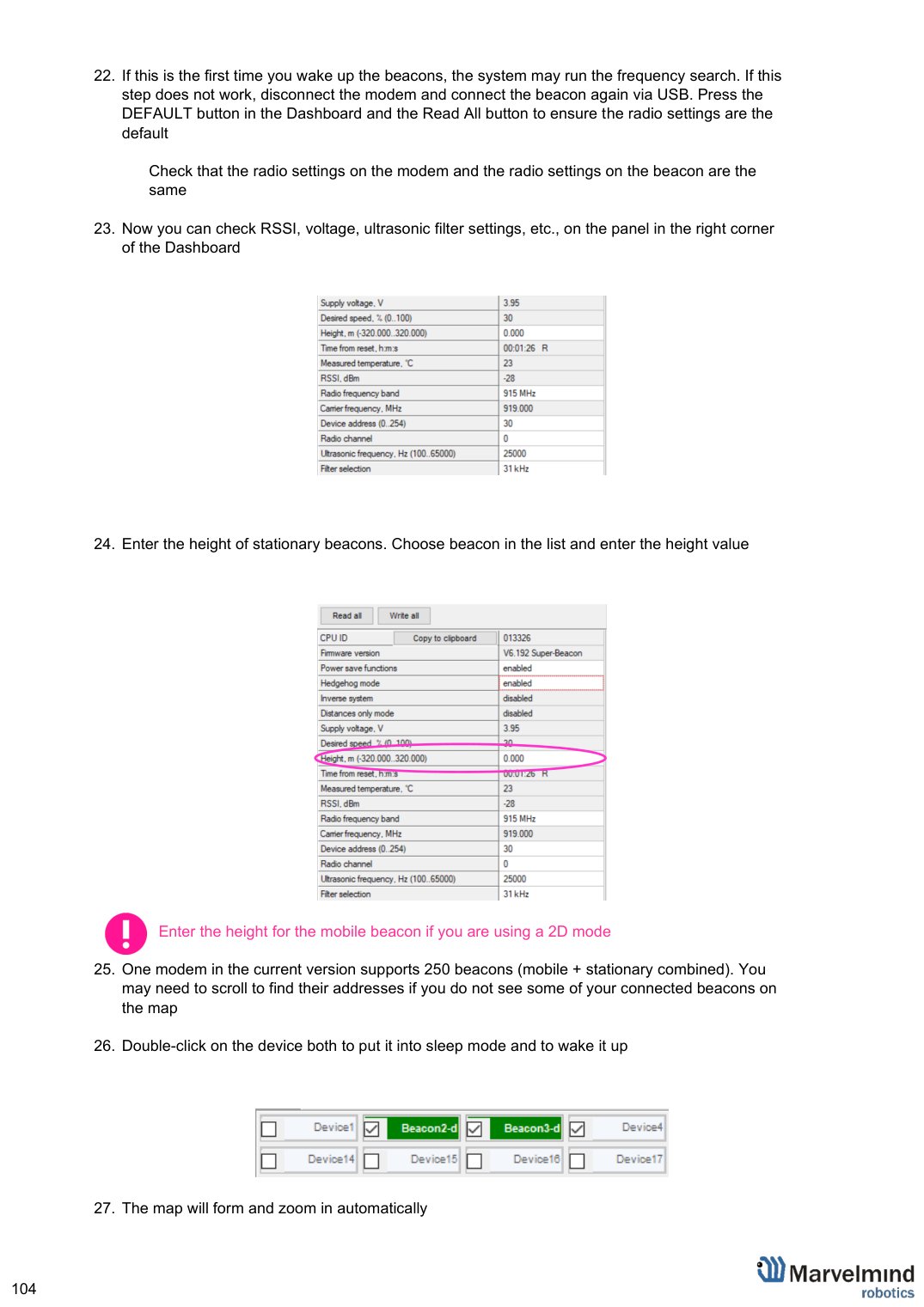
Top view of 2D configuration:

≈6-10m
≈4-6m


- More information about the placement can be found in the Placement Manual
- Connect the modem via USB to a Windows PC with the Dashboard installed
- Run the Dashboard. In the left corner of the Dashboard, the modem should be shown as connected
 Wake up all beacons by pressing the correct addresses on the Dashboard panel

 Wake up all beacons by pressing the correct addresses on the Dashboard panel
Only 4 stationary beacons may be in 1 submap. If you wake up more beacons, create a new submap for them, or it won’t be displayed on the map and in the table of distances.
- It may take up to 7-10 seconds for the beacons to wake up
- Notice that if the modem is not active and is not powered, the beacons will go into sleep mode automatically after 1 minute
- If this is the first time you wake up the beacons, the system may run the frequency search. If this step does not work, disconnect the modem and connect the beacon again via USB. Press the DEFAULT button in the Dashboard and the Read All button to ensure the radio settings are the default
Check that the radio settings on the modem and the radio settings on the beacon are the same
 Now you can check RSSI, voltage, ultrasonic filter settings, etc., on the panel in the right corner of the Dashboard
- Enter the height of stationary beacons. Choose beacon in the list and enter the height value
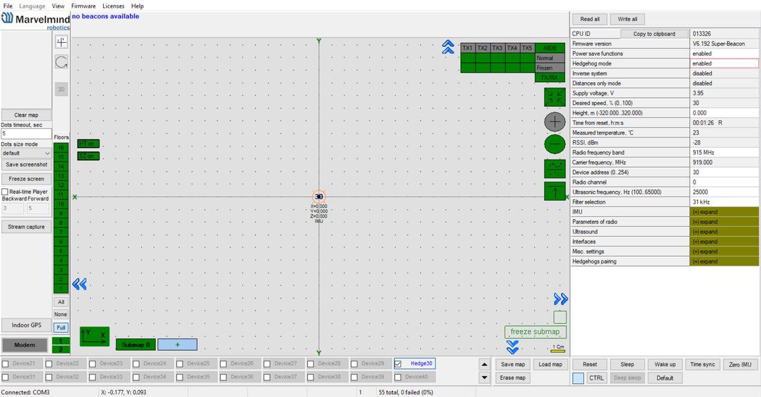 Now you can check RSSI, voltage, ultrasonic filter settings, etc., on the panel in the right corner of the Dashboard
 Enter the height of stationary beacons. Choose beacon in the list and enter the height value
Enter the height for the mobile beacon if you are using a 2D mode
- One modem in the current version supports 250 beacons (mobile + stationary combined). You may need to scroll to find their addresses if you do not see some of your connected beacons on the map
 Double-click on the device both to put it into sleep mode and to wake it up
- The map will form and zoom in automatically
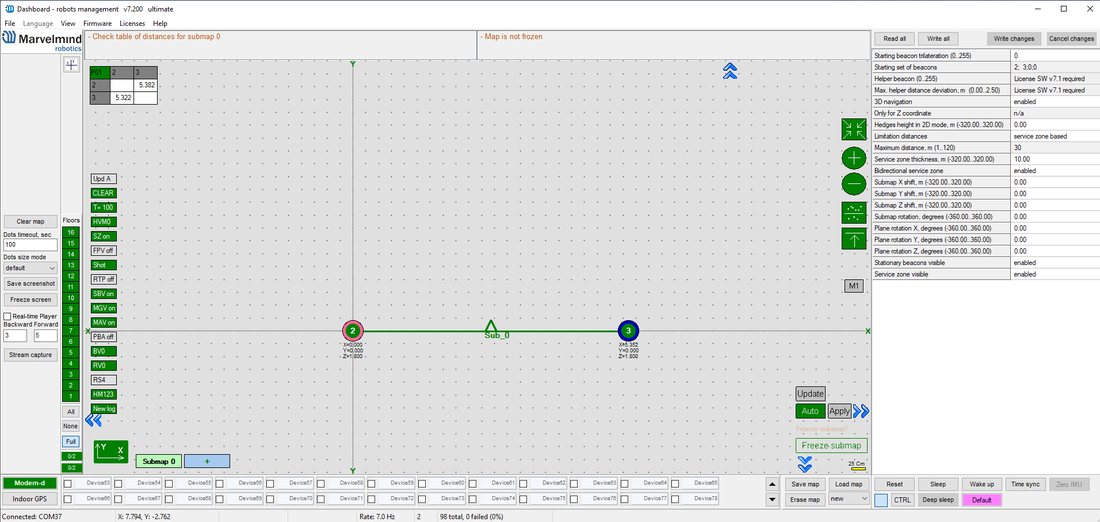
- If the map does not form well, check the table of distances in the left corner of the Dashboard. The cells must be colored white; it means the distances between the stationary beacons are measured correctly
 If you see some empty cells or marked yellow/red in the table, it indicates that distances between some beacons are measured inconsistently or not at all. Try to re-position them because there is usually an obstruction of some sort between the beacons. If you have any problems, check the Table of distances chapter
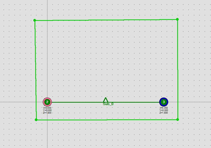
 Important: Build the service zone AFTER freezing the submap (see next step). Building it before freezing may result in an inaccurate zone if the submap continues to change. Make a service zone by clicking on the map with Shift + Left Mouse Button. Alternatively, use the new Auto-build service zone feature (left-click on the submap button, if a service zone has not been built yet it will be offered to build it automatically) – the Dashboard will automatically build a zone based on beacon positions. After auto-building, verify the zone matches the actual tracking area and adjust if needed. See the Submaps chapter for more details
 Double-click on the device both to put it into sleep mode and to wake it up
 If you see some empty cells or marked yellow/red in the table, it indicates that distances between some beacons are measured inconsistently or not at all. Try to re-position them because there is usually an obstruction of some sort between the beacons. If you have any problems, check the
  Important: Build the service zone AFTER freezing the submap (see next step). Building it before freezing may result in an inaccurate zone if the submap continues to change. Make a service zone by clicking on the map with Shift + Left Mouse Button. Alternatively, use the new Auto-build service zone feature (left-click on the submap button, if a service zone has not been built yet it will be offered to build it automatically) – the Dashboard will automatically build a zone based on beacon positions. After auto-building, verify the zone matches the actual tracking area and adjust if needed. See the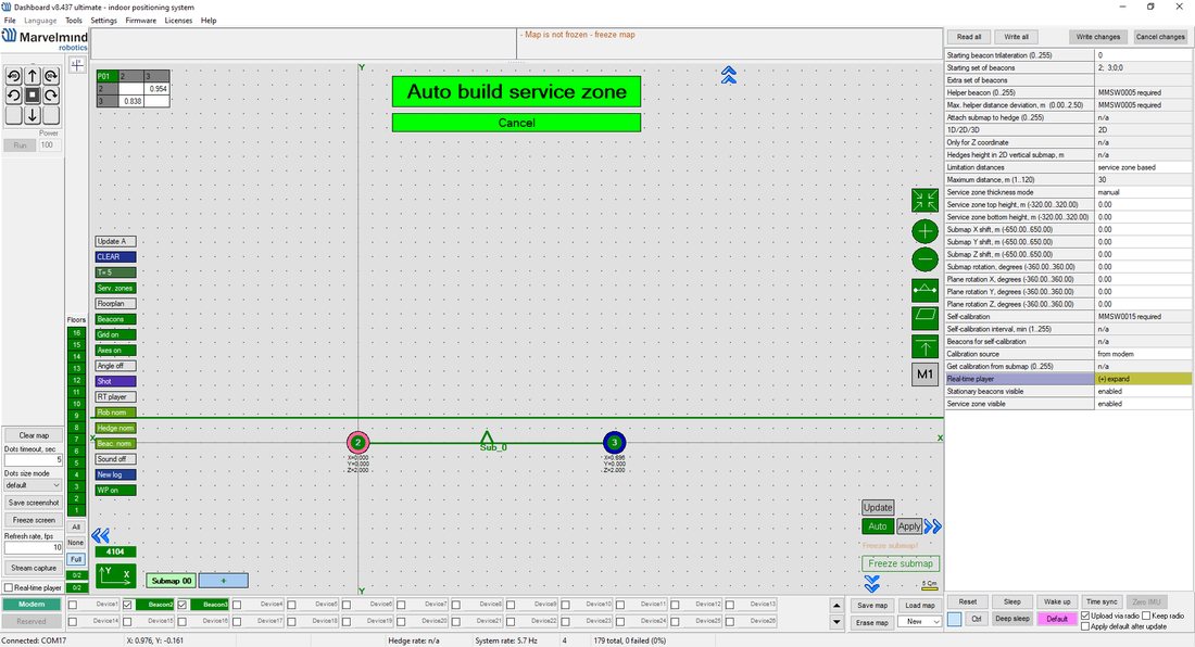
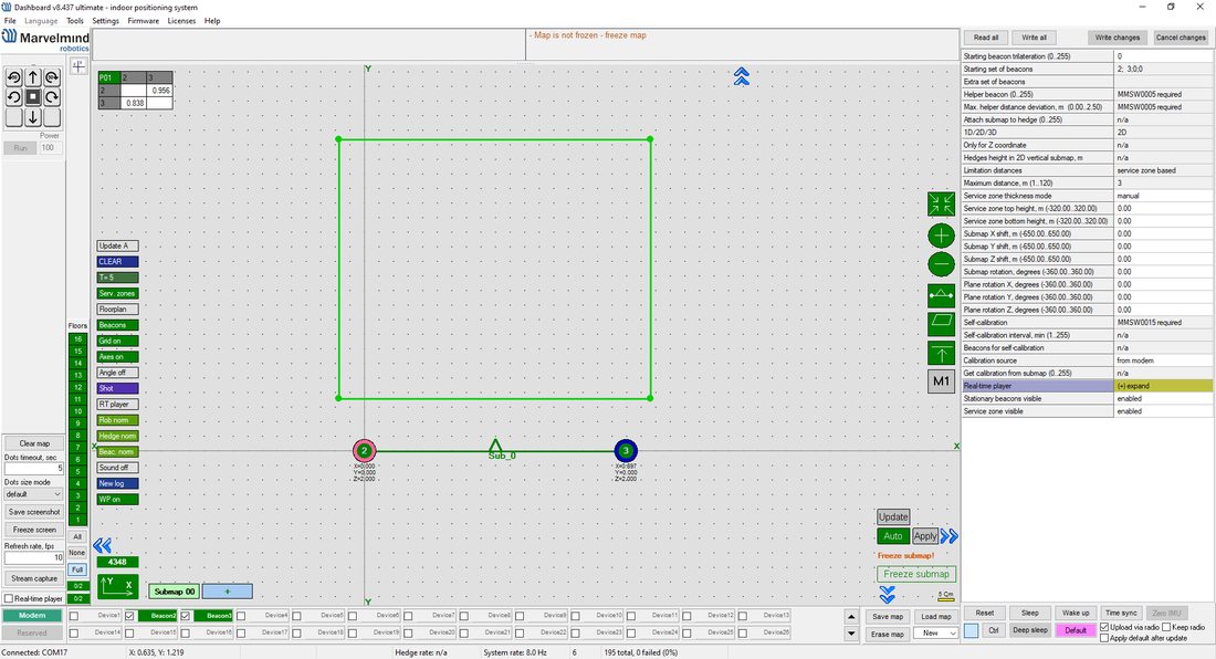
Freeze the Submap by clicking the button. Stationary beacons will stop measuring relative distances and will be ready to measure the distance from the mobile beacon(s)
 Turn on and wake up the mobile beacon by following the same steps as with the stationary beacon. More details are in our video
 - If you see on the devices’ panel in the Dashboard that the beacon is colored orange, it means there are some differences in some of the settings between beacons. For example, some sensors may be off, and some ultrasonic or radio settings may be different. You can manually change the sensors’ settings by clicking on the panel in the upper right corner of the Dashboard to change the cells from gray to green to turn on the sensor. It is recommended that the default settings on all beacons and the modem are used if this is your first time using the system
 If everything looks good and the table of distance is colored white, freeze the submap and the map
 The system is now fully operational
 - You can upload a picture/map of your room in the Dashboard. You can use a different picture for every floor. Go to Loading the floorplan (Help video)
Starter Set NIA-SmallDrone
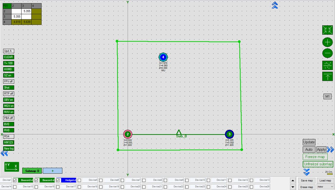
 Turn on and wake up the mobile beacon by following the same steps as with the stationary beacon. More details are in our
 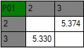 If everything looks good and the table of distance is colored white, freeze the submap and the map

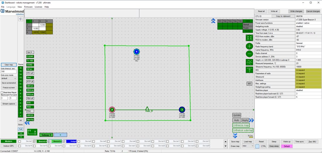 The system is now fully operational
 The steps below describe how to set up the system for the first time. Super-Beacon, Mini-TX beacons, and a modem are required.
- Unpack the system. Look at a similar unpacking video of HW v4.9. The videos have differences, but the basics are the same
- Charge all the beacons using a USB cable. Complete charging takes about 1-2 hours
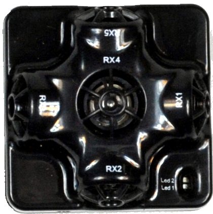
- Turn the beacons on
- Download SW Pack
- Update all the beacons:
 Unpack the system. Look at a similar
  Turn the beacons on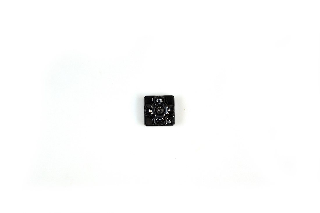
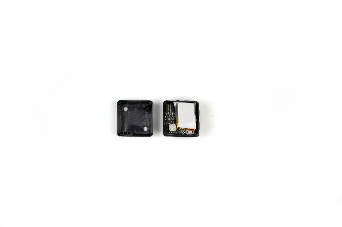
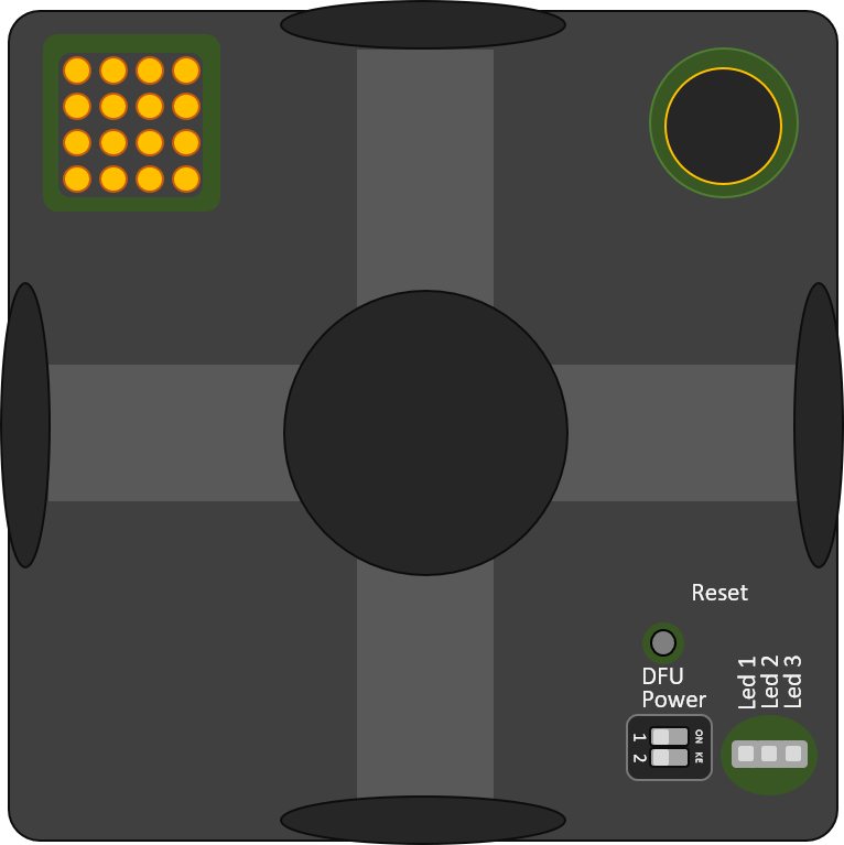
DIP switches
Reset button
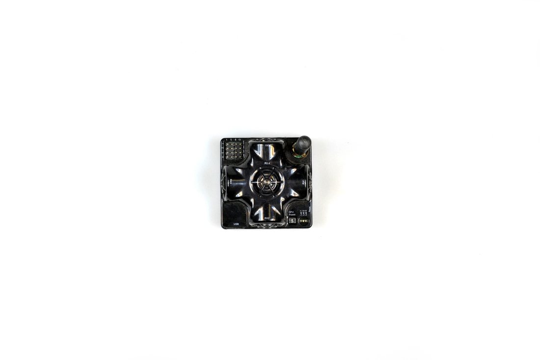
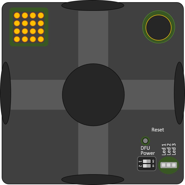
DIP switches
Reset
Reset button (on side)
Run the Dashboard and update the SW for all beacons and modem using Dashboard => Firmware => Choose the file => Program
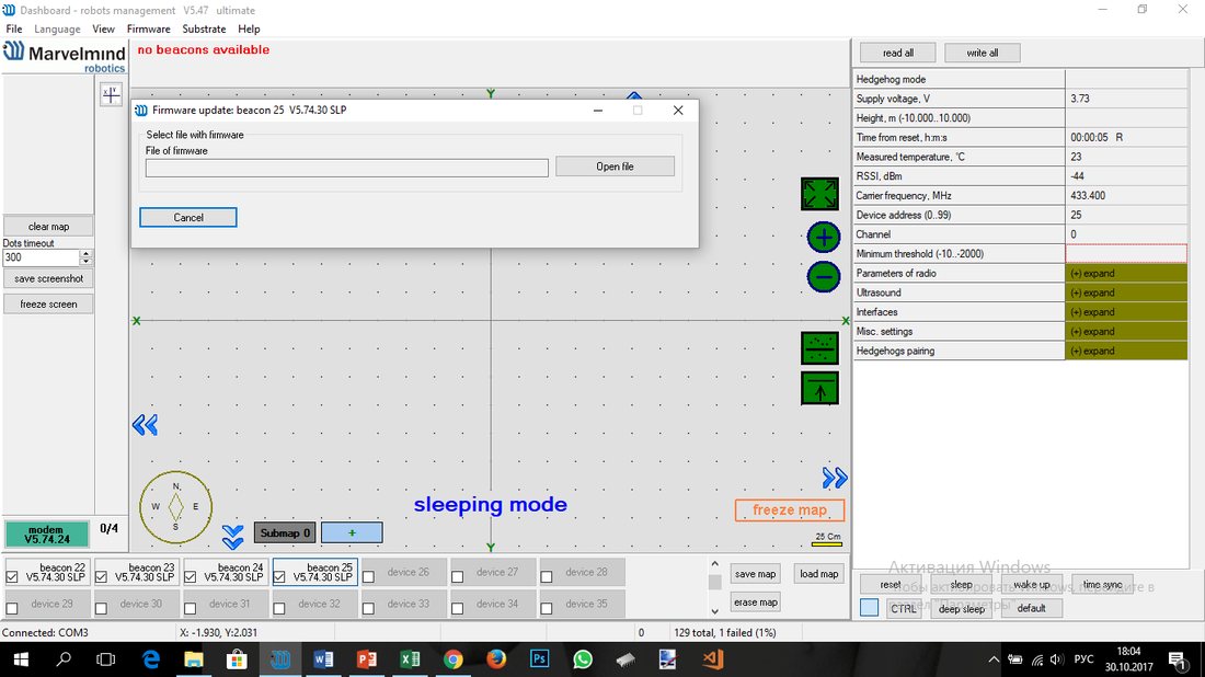

- If you receive “Windows protected your PC” window, check this chapter
- Note: On Windows 10 and later, the STM32 USB driver is installed automatically by the OS – no manual driver installation is required. The Dashboard does not show the driver download link in recent versions
- Make sure that that:
- You are programming the modem’s SW to the modem and the beacon’s SW to the beacon
- You are using SW for Mini-TX if you have Mini-TX and the SW from the same SW pack, i.e., the Dashboard SW, modem SW, and beacon SW must be from the same SW pack. Don’t mix SW releases
 You are using SW for Mini-TX if you have Mini-TX and the SW from the same SW pack, i.e., the Dashboard SW, modem SW, and beacon SW must be from the same SW pack. Don’t mix SW releases
If you face any issues during the software update, use DFU for updating the devices. Check out Software Updating via DFU Mode chapter.
If you have uploaded the latest firmware for all of the boards, you can start to activate the system:
- While the beacon or modem is connected to the Dashboard, click the DEFAULT button on the Dashboard to upload the default settings
 Write down the beacon’s address for future use or change the address at your convenience as shown here
- Mini-TX can operate only as mobile beacon, so “hedgehog mode” is enabled by default and cannot be disabled. You don’t need to enable hedgehog mode for Mini-TX manually.
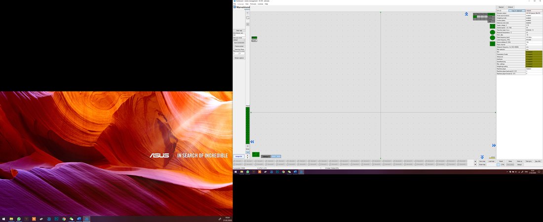 Write down the beacon’s address for future use or change the address at your convenience as shown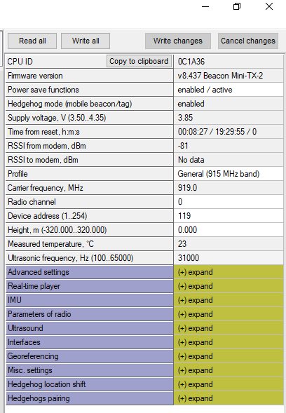
- Place the stationary beacons high on the walls vertically in a way that will provide optimal ultrasonic coverage. Write down the beacon’s height for future changes in the settings. The help video on installation can be found here
- Side view:

 Place the stationary beacons high on the walls vertically in a way that will provide optimal ultrasonic coverage. Write down the beacon’s height for future changes in the settings. The help video on installation can be found
 Top view:

≈6-10m
≈4-6m


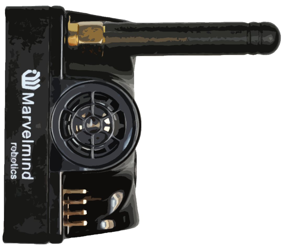
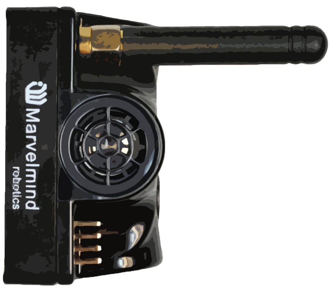
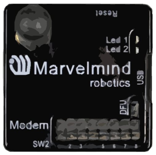
- Connect the modem via USB to a Windows PC with the Dashboard installed
- Run the Dashboard. In the left corner of the Dashboard, the modem should popup as you connect it
 Wake up all beacons by selecting them in the Dashboard on the panel
- It may take up to 7-10 seconds for the beacons to wake up
- Notice that if the modem is not active and is not powered, the beacons will go into sleep mode automatically after 1 minute
- The system may run the frequency search if it is the first time you wake up the beacons. If this step does not work, disconnect the modem and connect that beacon again via USB. Press the DEFAULT button in the Dashboard and the Read All button to make sure that the radio settings are the default ones
- Check that the radio settings on the modem and the radio settings on the beacon are the same
- Now you can check RSSI, voltage, ultrasonic filter settings, etc., on the panel in the right corner of the Dashboard
- Enter the height of stationary beacons. Choose beacon in the list and enter the height value
 Wake up all beacons by selecting them in the Dashboard on the panel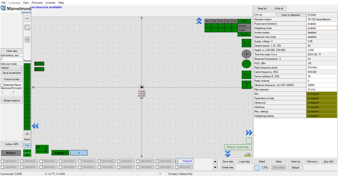
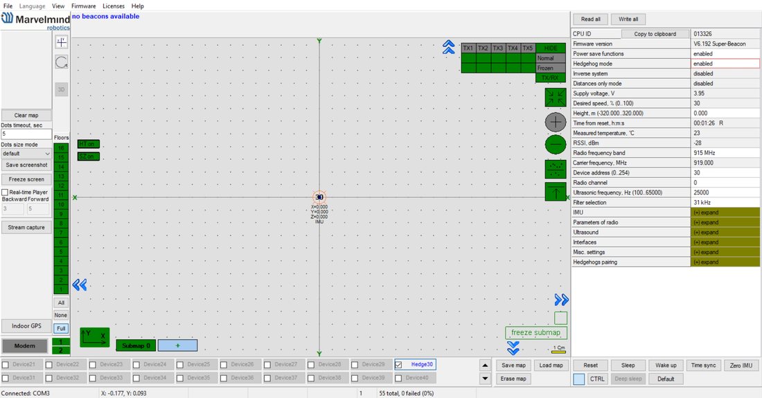
- One modem in the current version supports 250 beacons (mobile + stationary combined). If you do not see some of your connected beacons on the map, you may need to scroll to find their addresses
- Double click on the device to put it into sleep mode or wake it up
 Double click on the device to put it into sleep mode or wake it up
Only 4 stationary beacons may be in 1 submap. If you wake up more beacons, create a new submap for them; otherwise, they will not be displayed on the map and in the table of distances.
Build the map:
- Open the Dashboard
 Click on the Submap. You will see the table of distances
- It will automatically calculate the distances between the beacons. If some of them are red, it means that the beacons can’t calculate the distances by themselves. Check that there are no obstacles between the beacons and there is a direct line of sight
 If every cell is white, freeze the map by clicking the button. Stationary beacons will stop measuring relative distances and will be ready to calculate distance from the mobile beacon(s)
- Build the service zone for the submap after freezing it. Use Shift+Left Mouse Button clicks on the map to draw the zone boundary. Alternatively, use the Auto-build service zone feature (left-click on the submap button; if the service zone has not been built yet, Dashboard will offer to build it automatically). After building, verify the zone covers the intended tracking area and adjust if needed. For drones, it is especially important to define the service zone correctly. See the Submaps chapter for details
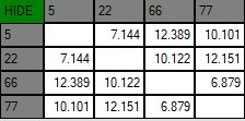 Click on the Submap. You will see the table of distances
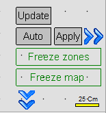 If every cell is white, freeze the map by clicking the button. Stationary beacons will stop measuring relative distances and will be ready to calculate distance from the mobile beacon(s)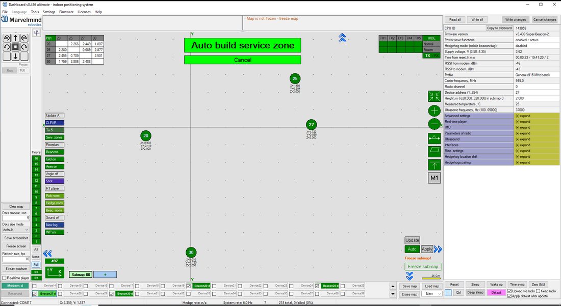
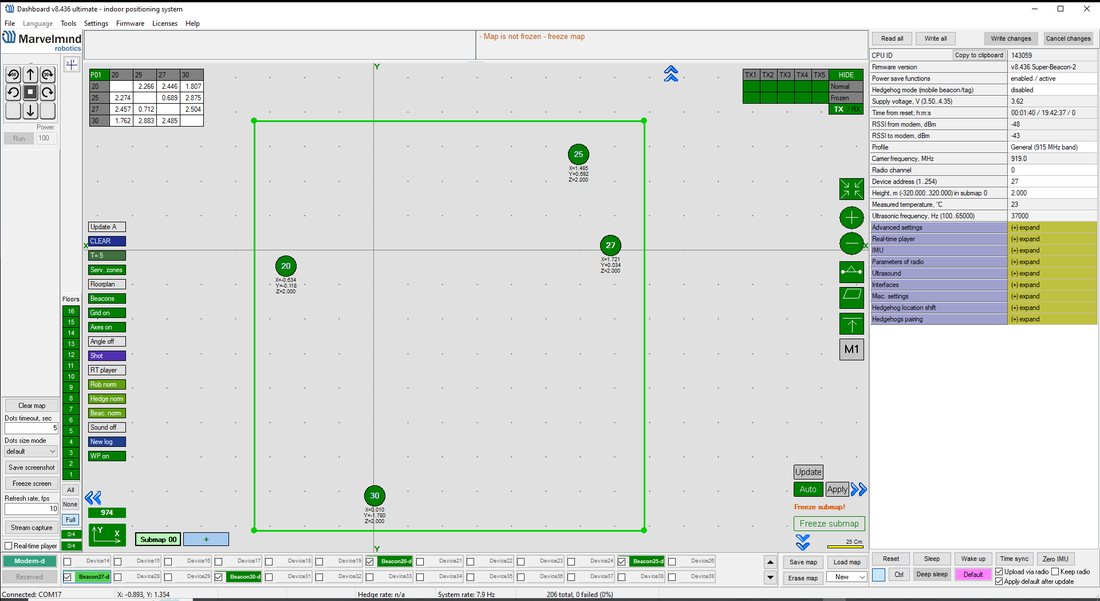
- Turn on and wake up the mobile beacon, following the same steps as the stationary beacon. Here is a helpful video
- If you see on the devices’ panel in the Dashboard that the beacon is colored orange, it means there are some differences in some of the settings between beacons. For example, some sensors may be off, and some ultrasonic or radio settings may be different. You can manually change the sensors’ settings by clicking the panel in the upper-right corner of the Dashboard to turn the cells from gray to green and turn on the sensor. It is recommended that the default settings on all beacons and the modem be used if this is your first time using the system
- After you freeze the map of stationary beacons, wake up the mobile beacon. It will be traceable in 5-7 seconds
 The system is now fully operational. Tip for drones: to increase the location update rate, consider switching to a 500 kbps radio profile. See: how to increase location update rate
 Starter Set Industrial-NIA-01
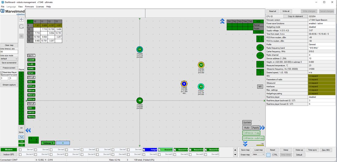 The system is now fully operational. Tip for drones: to increase the location update rate, consider switching to a 500 kbps radio profile. See:
 The steps below describe the first setup of the system.
 This is a Non-Inverse Architecture. You can find the description and comparison of architectures here.
 Pay attention: Industrial beacons have different HW and SW.
Read more on the Industrial Beacon page.
Industrial beacons have no battery, so use a power supply cable.
Use specific Industrial beacon’s SW for specific Industrial beacons.
Do not disassemble the Industrial beacons. Otherwise, the warranty will be lost.
Version 3 of Industrial RX (from April 2022) supports ONLY +5 V power supply. Don’t use a +12 V power supply converter for this version, it will burn the beacon!
Version 3 doesn’t have UART RX, but now it is possible to use an Interface connector as a power supply for this version.
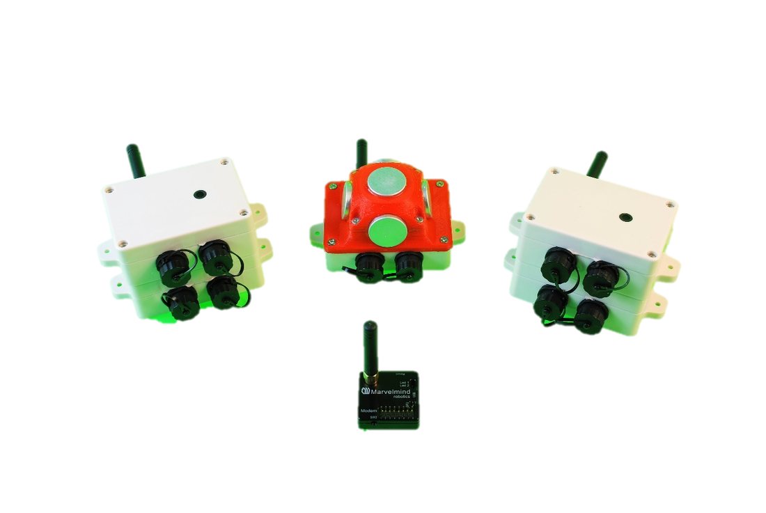
- Unpack the system. Take a look at the similar unpacking video for HW v4.9. They are different, but they have some similar basics
- You do not have to charge Industrial beacons; they have no battery
- You do not have to turn it on – Industrial beacons are permanently ON
- Download SW Pack
- Update all the beacons:
 Unpack the system. Take a look at the similar
  You do not have to turn it on – Industrial beacons are permanently ON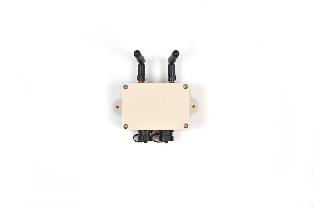
Magnetic DFU switch side
Magnetic Reset side
Run the Dashboard and update the SW for all beacons and modem using Dashboard => Firmware => Choose the file => Program
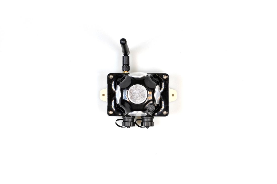
Magnetic DFU switch side
Magnetic Reset side
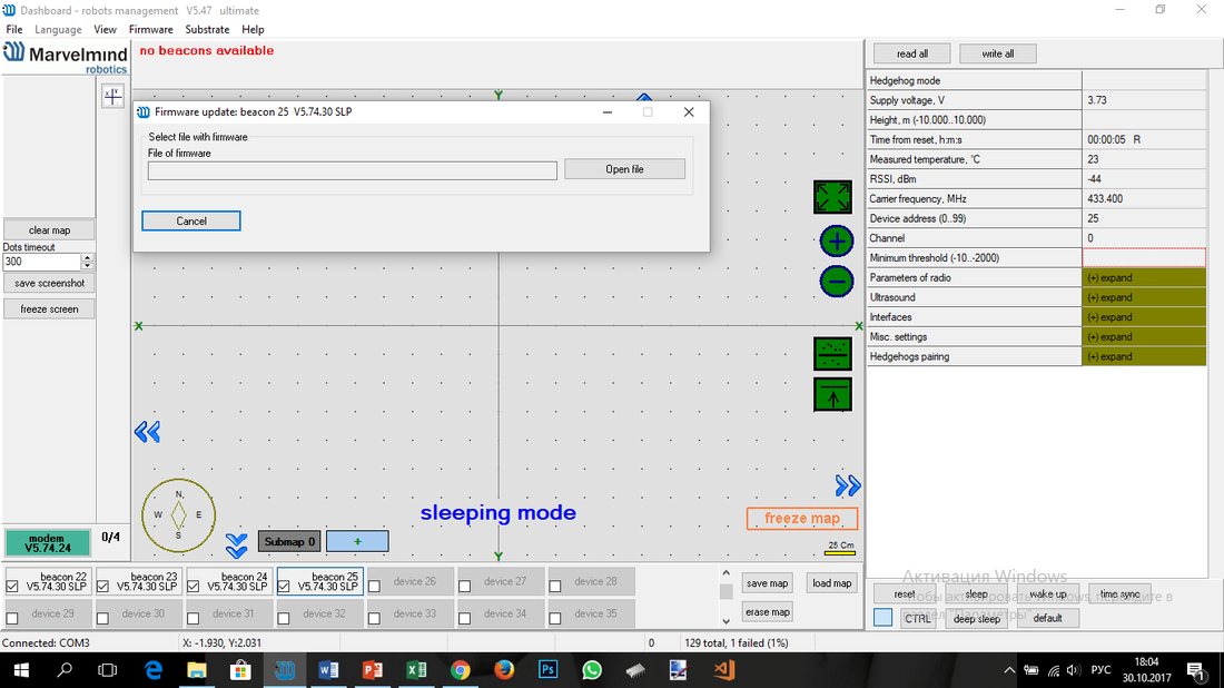

If you receive “Windows protected your PC” windows, check this chapter
Note: On Windows 10 and later, the STM32 USB driver is installed automatically by the OS – no manual driver installation is required. The Dashboard does not show the driver download link in recent versions
Ensure that:
- 7.1 You are programming the modem’s SW to the modem and the beacon’s SW to the beacon
- 7.2 You are using SW for Industrial beacon if you have Industrial beacons, and you have the SW from the same SW pack, i.e., the Dashboard SW, modem SW, and beacon SW must be from the same SW pack. Don’t mix SW releases
 If you face any issues during the software update, use DFU for updating the device. Check out Software Updating via DFU Mode chapter.
If you have uploaded the latest firmware for all the boards, you can start to activate the system:
- While the beacon or modem is connected to the Dashboard, click the DEFAULT button on the Dashboard to upload the default settings
- Write down the beacons’ addresses for future use or change the address at your convenience as shown here:
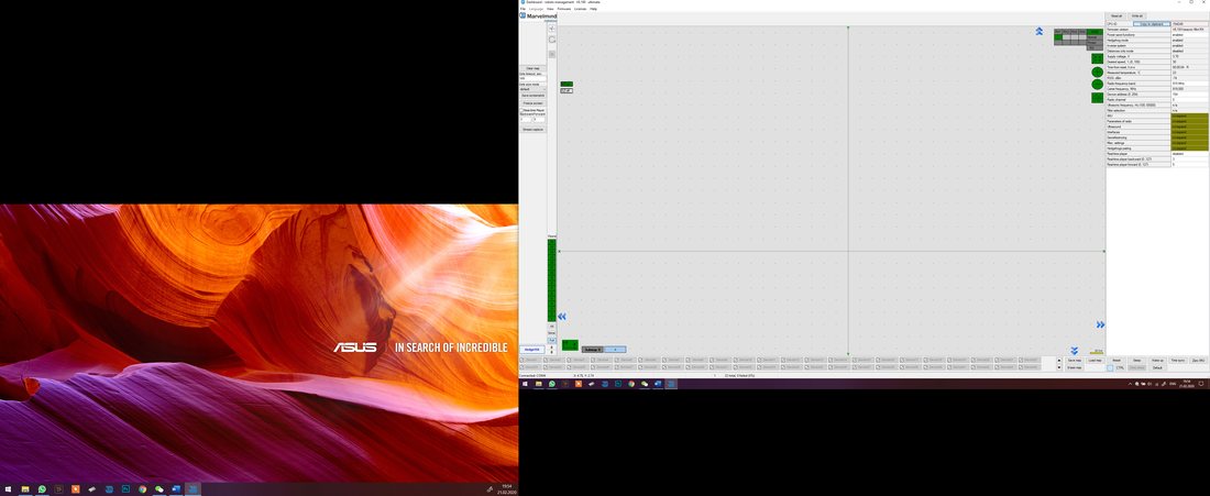
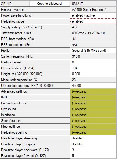
Choose the Industrial-TX-25 beacon and enable “Hedgehog mode”. Use this beacon as a mobile beacon in the future. Here is a help video
- Press the RESET (Industrial beacons have magnetic re button on your beacons and modem after programming
- After programming devices with the latest software, the modem and beacons are ready for use
- Place the stationary beacons high on the walls vertically in a way that will provide optimal ultrasonic coverage. Write down the beacon’s height for future changes in the settings. The help video on installation can be found here
- Side view:
 After programming devices with the latest software, the modem and beacons are ready for use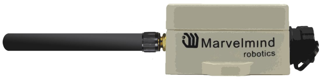
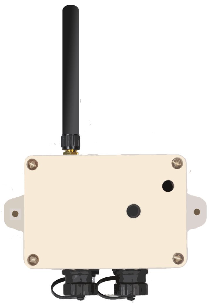
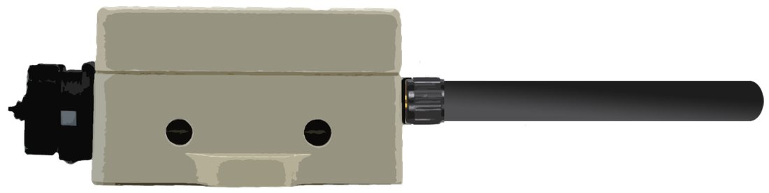
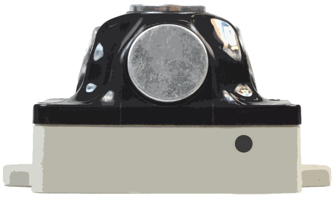



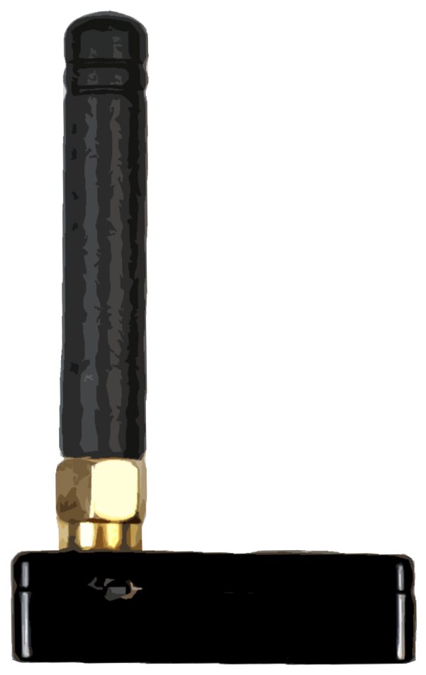
- Stationary beacon
- Stationary beacon
- Stationary beacon
- Mobile beacon
- Modem beacon
Top view:
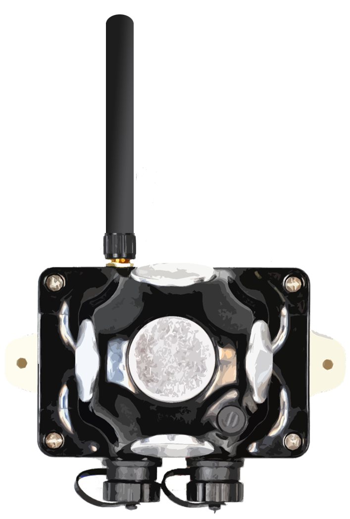

≈6-10m
≈4-6m


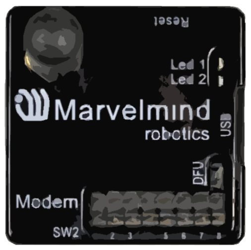
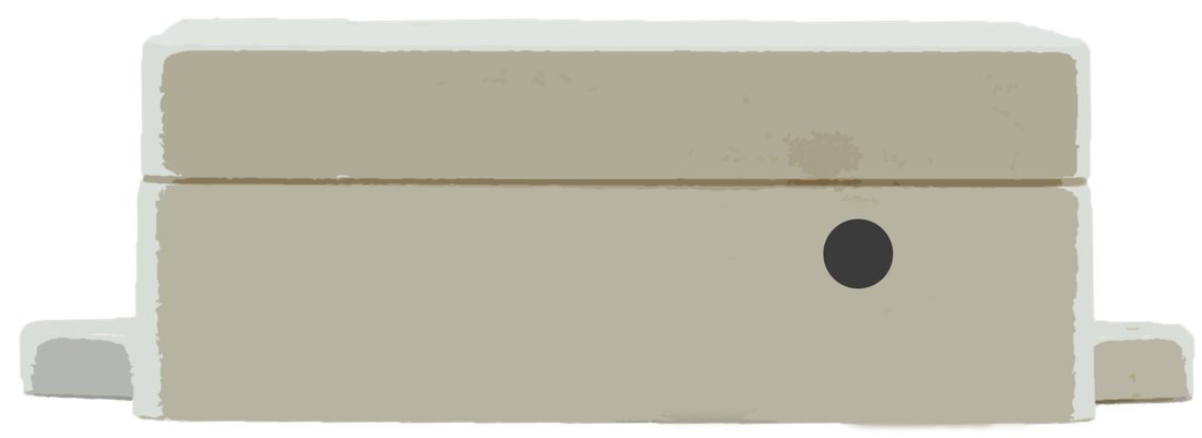
- Connect the modem via USB to a Windows PC with the Dashboard installed
- Run the Dashboard. In the left corner of the Dashboard, the modem should be shown as connected
- Wake up all beacons by clicking on the buttons in the Dashboard on the panel
- It may take up to 7-10 seconds for the beacons to wake up
- If the modem is not active and is not powered, the beacons will go into sleep mode automatically after 1 minute
- The system may run the frequency search if it is the first time you wake up the beacons. If this step does not work, disconnect the modem and connect that beacon again via USB. Press the DEFAULT button in the Dashboard and the Read All button to make sure that the radio settings are the default ones
- Check that the radio settings on the modem and the radio settings on the beacon are the same
- Now you can check RSSI, voltage, ultrasonic filter settings, etc., on the panel in the right corner of the Dashboard
- Enter the height of stationary beacons. Choose beacon in the list and enter the height value
 Wake up all beacons by clicking on the buttons in the Dashboard on the panel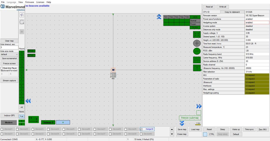

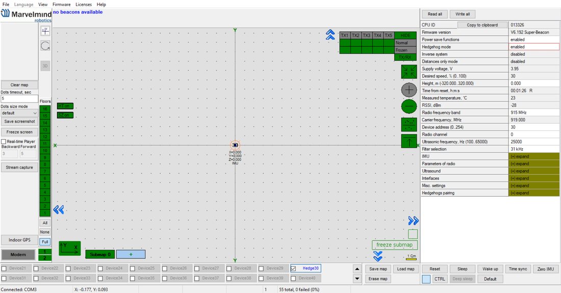
Enter the height for the mobile beacon if you use 2D mode
One modem in the current version supports 250 beacons (mobile + stationary combined). If you do not see some of your connected beacons on the map, you may need to scroll to find their addresses
Double click on the device to put it into sleep mode or wake it up
Only 4 stationary beacons may be in 1 submap. If you wake up more beacons, create a new submap for them. Or it won’t be displayed on the map or in the distances table.
Now you can proceed to building the map:
Industrial-RX beacons cannot build the map automatically, so you have to make it manually.
- Open the Dashboard. You will see the table of distances
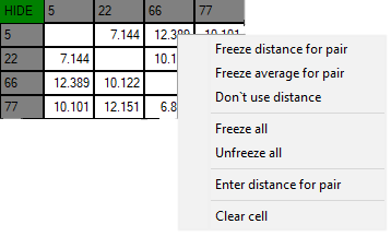
- Right click on the cell where you want to enter the distance. An additional menu will open; there you can control the distances. Choose Enter distance for pair to enter the value

- Now, enter the measured value (measure it with a laser distance meter or so). Those values will not change until you unfreeze or clear them. Even if beacons had been moved, distance would stay. Be careful with frozen cells because a small mistake can significantly impact your tracking!
- Repeat for all cells
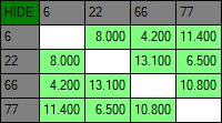
Freeze the map by clicking the button. Stationary beacons will stop measuring relative distances and will be ready to measure the distances from the mobile beacon(s)
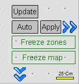
- Build the service zone for the submap after freezing it. Use Shift+Left Mouse Button clicks on the map to draw the zone boundary. Alternatively, use the Auto-build service zone feature (right-click on the submap button) to automatically build a zone based on beacon positions. For 3D maps with multiple submaps, use the 3D auto-build feature. After building, verify the zone covers the intended tracking area and adjust if needed. See the Submaps chapter for details
- Turn on and wake up the mobile beacon, following the same steps as the stationary beacon. Here is a help video
- If you see on the devices’ panel in the Dashboard that the beacon is colored orange, it means there are some differences in some of the settings between beacons. For example, some sensors may be off, and some ultrasonic or radio settings may be different. You can manually change the sensors’ settings by clicking on the panel in the upper right corner of the Dashboard to change the cells from gray to green to turn on the sensor. It is recommended that the default settings on all beacons and the modem be used if this is your first time using the system
- After you freeze the map of stationary beacons, wake up the mobile beacon. It will be traceable within 5-7 seconds
 The system is now fully operational
 Turn on and wake up the mobile beacon, following the same steps as the stationary beacon. Here is a
 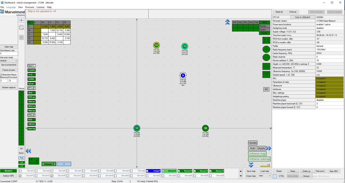 The system is now fully operational