Autonomous Boat Navigation In GNSS-Denied Areas With ±2cm Accuracy
Autonomous boats have many names: roboats, unmanned surface vessels, unmanned surface vehicles, and self-steering boats. It is the same thing. Autonomous robots are simply a variant of autonomous robots operating on the water’s surface.
There are many use cases for autonomous boats that we have been contacted about:
- Delivering goods and passengers
- Navigating channels and harbors for inspections
- Patrolling
- Autonomously docking to larger ships, for example, after performing a rescue operation
- Using underwater sonars for underwater inspections and object detection
We focus on autonomous boats without GPS – not on maritime ships or large vessels. The article below discusses self-steering boats working in channels, tunnels, indoors, and underground – in any GNSS-denied areas – not in the open sea or lakes with easy positioning and navigation using GPS.
Example of precise tracking of racing boats without GPS
How autonomous boats work
Autonomous boats like autonomous robots or self-driving cars rely on several key systems to be autonomous:
- Localization
- Obstacle detection and avoidance
- Mobility or propulsion
Since crewless surface vehicles interact with the world and users and perform some practical tasks; they also have to be capable of the following:
- External communication and connectivity
- User interface
- Payload carrying capability
Autonomous boats get tasks from the end users or operators or larger ships and perform their tasks autonomously based on the localization systems and obstacle detection and avoidance systems. They rely on the controllers and processors, memory, and programs to operate with the rules. They are indeed simply a subset of autonomous robots.
Thus, like any autonomous robot, autonomous boats have sensors, processors, and actuators.
Self-steering boats are typical autonomous robots but on the water surface.
There are many other ways for localization, for example, LIDARs. But those are not recommended for the boat positioning because:
- Expensive
- Don’t work well in fog or rain
- Blinded by sun, light, reflections, infrared sources
Cameras seem to be better than LIDARs, in theory. But in practice, still, robust and precise positioning based on cameras is very challenging to implement, and their performance is heavily affected by lighting conditions, water reflections, fog, and rain.
Therefore, for autonomous boats in GNSS-denied areas, we recommend external RTLS systems such as Marvelmind Indoor “GPS” or UWB as the primary positioning source. The best performance is usually provided, but a sensors fusion approach is.
Problem
When GPS/GLONASS/Galileo/Beidou is available, navigation of autonomous boats is a relatively straightforward task, particularly when some flavors of RTK GPS are available. But it is a significantly more challenging task in GPS/GNSS denied areas, for example:
- Channels surrounded by tall buildings
- Tunnels
- Closed viaducts
- Under the bridges
- Underground
Even when GPS is available, RTK GPS is not available, but an autonomous boat must dock with a moving ship.
Another type of problem arises when several boats must move in sync close to each other, maintaining the distances, like swarm boats.

Solution
The solution is a real-time locating system (RTLS) or indoor positioning system (IPS), for example, Precise Indoor “GPS” by Marvelmind.
Don’t be confused with the word indoor. If it is indoors, it can work indoors and outdoors. But most outdoor navigation systems, for example, GPS, can’t work indoors because GPS satellites’ radio signal doesn’t propagate through walls or ceilings.
How RTLS for self-steering boats work
Navigation for autonomous boats without GPS relies on one of the types of real-time locating systems (RTLS). Such a system doesn’t substantially differ from a similar RTLS system for autonomous robots or AGVs.
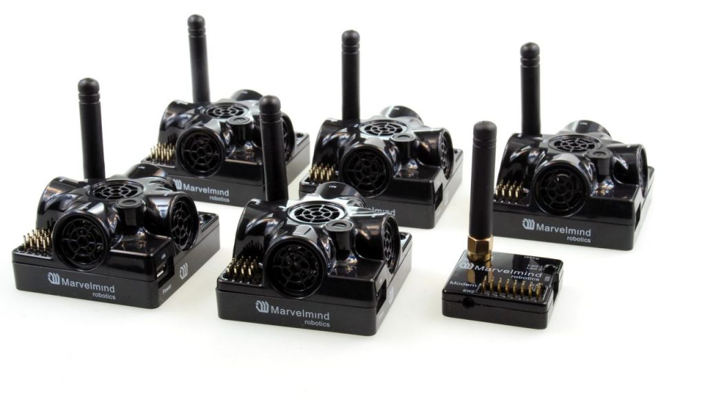
The RTLS consists of three main elements:
- Stationary beacons (anchors) – the equivalent of GPS satellites. They are used as coordinate reference points for positioning
- Mobile beacons (tags) installed on the boat
- Modem/router – a central device to control the system and to get the location data of the boat in one place – ground stations in GPS
Self-steering boats can get location data, including gyro and accelerometer data, from an inertial measurement unit (IMU) directly from the mobile beacon.
Or they can be remotely controlled by an external brain getting their location and IMU data via the modem – the system’s central controller. Though the self-steering boats will be remotely controlled, it doesn’t make them non-autonomous. They will remain autonomous. Their central controller will be outside of their main body.
Quick and dirty recommendations on configurations
If mobile beacons are NOT exposed to water or dust, or mist:
In this case, tracking boats is not different from the tracking robots/AGVs/vehicles in 2D. Check the Robotics page for more details. In short:
- Starter Set Super-MP-3D – the simplest and the most versatile set to start with
- Starter Set Super-MP-3D + Super-Beacon – if you want Location+Direction
- Starter Set Super-MP-3D + Super-Beacon + 2 x Omni-Microphones – if your area is large (20x20m or more) or your stationary beacons are 30 degrees from the horizon or lower. You will be able to build robots with this kind of driving capabilities
If mobile beacons are exposed to water or dust, or mist:
Then, the recommended configuration:
- IA
- Super-Beacons hidden inside the boat and Omni-Microphones sticking out for Location and Direction very much alike in our robot Boxie
If you want even more protection, the more rigid Industrial-RX with Omni shall be your choice for mobile beacons.
Customized configurations
For the most recommended configuration for your particular case with your specific requirements, please email us at info@marvelmind.com.
Autonomous boats vs. other types of autonomous robots
Autonomous boats vs. autonomous wheeled robots/AGVs:
- Both types operate primarily in 2D
- There are typically more obstacles and obstructions for the wheeled robot
- The wheeled robot has an odometer as an additional source of location information
- Water is a severe hazard to electronics – more problematic for boats. Saltwater is even more dangerous
Autonomous boats vs. autonomous drones:
- It is easier for the boat because it is 2D
- There is typically less obstruction
- Drones fall. Boats sink. Still, a drone’s life is more dangerous and generally short
- Boats can stay autonomous much longer than drones because of batteries and energy supply in general
"Lie, fishing stories, election promises, statistics, and IPxx" - be realistic
Remember that the right level of ingress protection guarantees that the devices won’t be killed with a short time of exposure to water or rain splashes. The IPxx certificate doesn’t say anything about prolonged exposure or exposure to something that is not clean, fresh water, for example, dirty, oily, salty water, snow, etc.
Yes, the IPxx devices will likely survive those exposures as well. But no guarantees. That is an open secret with all IPxx fine prints. Be aware and be realistic with expectations.
What to do?
- Clean with fresh water after use so that dirt or salt, or similar pollutants wouldn’t destroy the protective membranes
- Make sure that ice or frost won’t puncture the membranes. Don’t let the water freeze on the beacons
- For long-time exposure to rain, use special umbrellas – similar to outdoor cameras. Maintain a line of sight to stationary beacons
- The outdoor beacons can withstand rain exposure or water splashes, but the tracking performance is not guaranteed. The devil is in detail
- After assembly, cover all metal parts with special saltwater-protecting lacquer. Remember not to spray over the membranes
Recommendations for the long-term outdoor or ingress exposure
- Do all kinds of shields and umbrellas for the beacons so that the rain, dust, sun wouldn’t expose the beacons directly
- Shields and umbrellas must not create ultrasound shadows and non-line of sight
- Shields and umbrellas must be made and placed so that the sound of drops wouldn’t interfere with the ultrasound pulses that sound alike
- With indirect exposure, often, even Super-Beacons that have virtually no ingress protection, can work well outdoor for a long time
- Remember that with negative temperatures the internal LiPol batteries cannot be charged without a risk of battery failure and even a fire
Questions and answers
2023.Mar.11: Indoor positioning system for autonomous boats
Hello Marvelmind team,
We are currently in the process of testing and setting up the indoor
positioning system for our autonomous boats. Our current setup consists
of three stationary beacons mounted on tripods and two mobile beacons
with omni microphones mounted on a boat.
you are playing 2D, it is highly advisable to use either two stationary
beacons or 2+2 stationary beacons to have fully overlapping submaps.
you place 3 stationary beacons, the system will automatically move to
3D tracking, which you don’t need and is less reliable for 2D since
there must be a line of sight to 3 stationary beacons—not 2 stationary
beacons as for 2D.
While we are achieving
reasonable tracking of the boat within the IA-Architecture,
we have
several questions that we hope you can address.
With the current setup we get a total update rate of 6Hz. Is it
reasonable to choose the closest update rate in the modem settings
(8Hz)?.
Or is the calculation of the positioning much faster and will
give us better, more-up-to-date data with a higher update rate (for
example 16 Hz). Although the payload and radio settings only allow the
6Hz. We dont want to add more lattency to slow down the communication.
How to increase the location update rate and reduce latency?
– there are several options to increase the update rate.
We encountered some confusion regarding the pinout for the super-beacons
as depicted in the manual. The illustration provided lacked clarity on
the viewing angle for the pinout.
We’ve attached an illustration for
your reference and would greatly appreciate your confirmation regarding
its correctness.
Additionally, could you please clarify whether the SPI
connection requires an SS pin or if it operates as a slave
automatically?
Furthermore, we couldn’t find information regarding the
voltage specifications for the UART and SPI connections of the beacon.
Are these connections operating at 5V or 3V?
Upon reviewing the provided software pack, we found the dashapi to be
somewhat complex and were unable to find guidance on outputting IMU
data.
For our current application, we are utilizing the C example as it
meets our requirements adequately. However, we have some inquiries
regarding the IMU data. When obtaining RAW IMU data directly from the
beacon, we achieve an update rate of 100Hz, whereas obtaining the same
data from the modem results in an update rate of 6Hz in our setup.
is a more complex architecture requiring a separate modem and a special
SW to receive fast 100-Hz IMU data, but it is possible and available.
Could
you confirm whether these values represent the RAW IMU data at 6Hz or if
they are accumulated values over the 6Hz interval?
Understanding this
distinction would be beneficial as it would inform whether direct
accumulation of RAW IMU data from the beacons is necessary.
Or is the processed IMU data the solution made for this difference in
update rate?
To determine the direction and angle of the boat, we have paired two
mobile beacons via radio on the boat.
Regarding IMU Fusion for angle
calculation, could you provide insight into the procedure? Is the
pairing through radio sufficient given the discussed update rates, or
would UART be more suitable for IMU Fusion? Following pairing and
enabling the center location, will the updated IMU represent the
calculated fused IMU or two separate sensor outputs?