Basics of the system
This chapter as a clean, readable HTML page.
The “Basics of the system” chapter of the Operating Manual, reproduced as a real HTML page. Anything unclear? Open the original PDF of just this chapter (pages 19-30) (also pinned top-left). Hub: all chapters.
Here are examples of the Starter Sets:
What’s in the Box Starter Set Super-MP-3D:
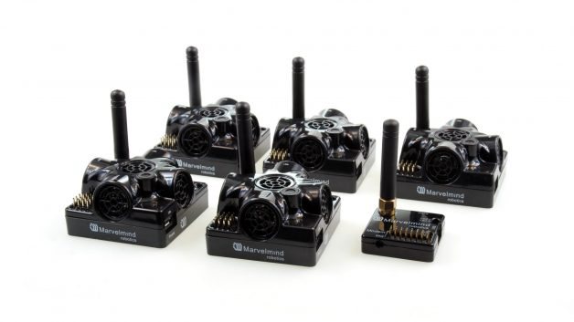
Starter Set IA-04-2D-Badge:
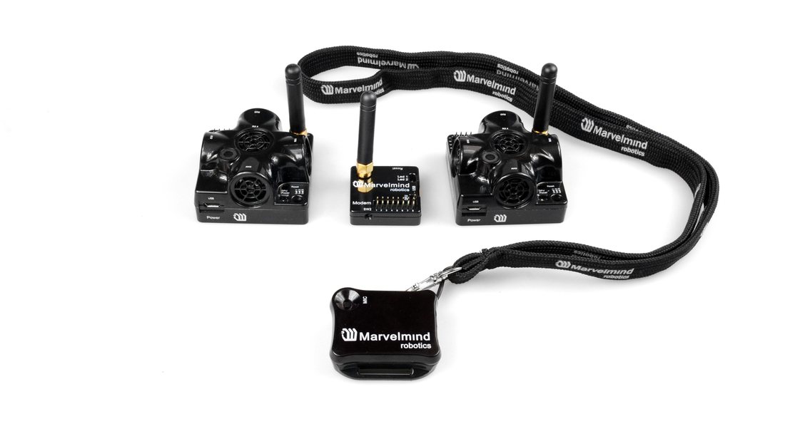
 *This is just an example of two starter sets.
You can see more options on our website: Products.
Indoor Navigation System Architectures
Marvelmind Indoor Navigation System provides high-precision (±2 cm) indoor coordinates for autonomous robots and systems (“indoor GPS”). The scheme below briefly describes the system’s key elements.
 IA and NIA SW differ.
For IA, you should use stationary beacons with different frequencies.
Below, you can see 3 types of architectures: Non-Inverse (NIA), Inverse (IA), and Multi-frequency NIA (MF NIA):
Inverse Architecture (IA)
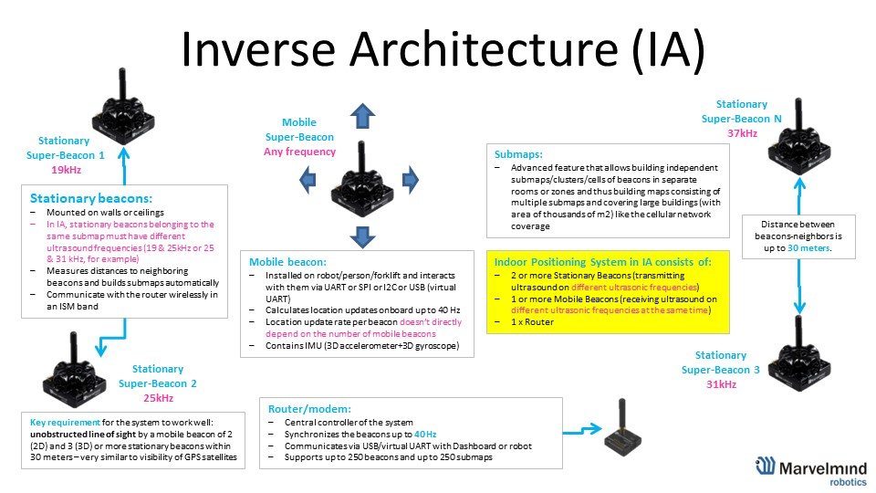 For IA, you should use stationary beacons with different frequencies.
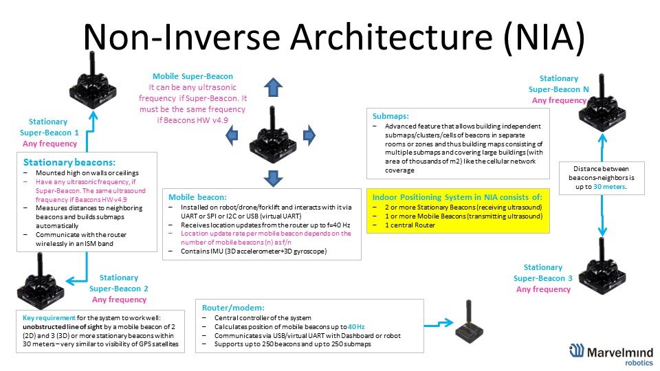 Non-Inverse Architecture (NIA)
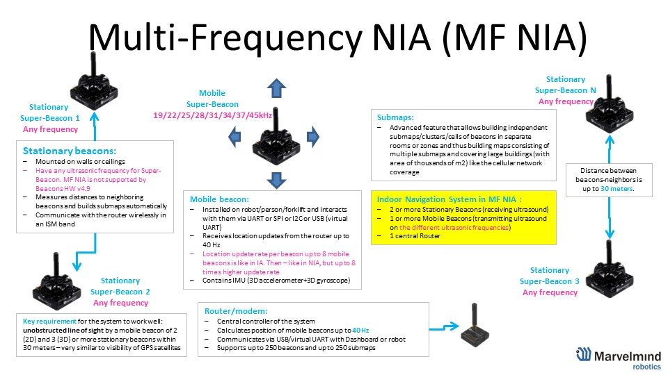 License MMSW0004: MF NIA support is needed to use MF NIA
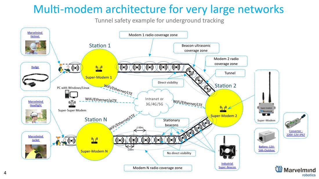 Multi-modem Architecture for Very Large Networks
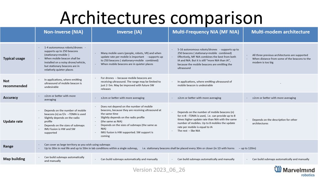 Architectures Comparison Table
Here are the tutorial videos about architectures:
 Help: Inverse Architectures (IA) vs. Non-Inverse Architectures (NIA)
NIA vs. IA vs. MF NIA – how to choose?
Architectures’ Elements
A map is a system unit that includes submaps, stationary beacons, and service zones. Ultrasonic signals from the stationary beacons of this submap ensure the positioning of mobile beacons.
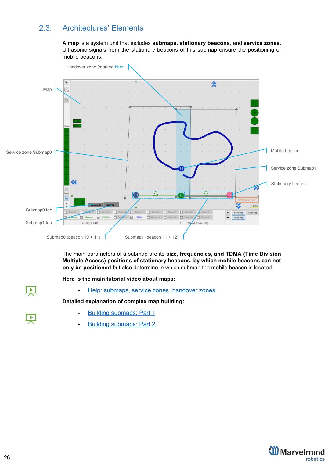
The main parameters of a submap are its size, frequencies, and TDMA (Time Division Multiple Access) positions of stationary beacons, by which mobile beacons can not only be positioned but also determine in which submap the mobile beacon is located.
 Here is the main tutorial video about maps:
Help: submaps, service zones, handover zones
Detailed explanation of complex map building:

Indoor “GPS” System Close-up and Internal View
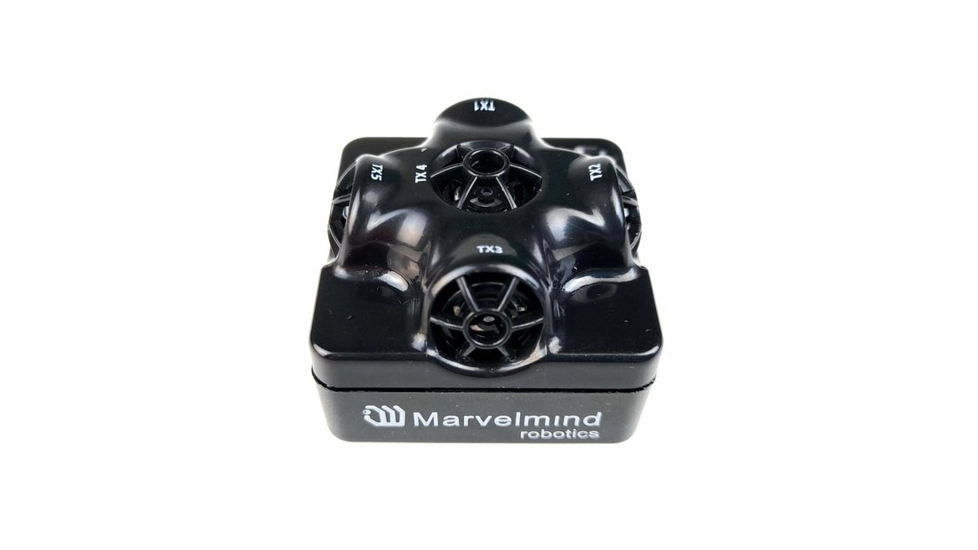
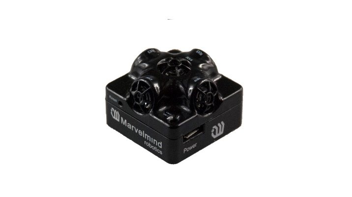
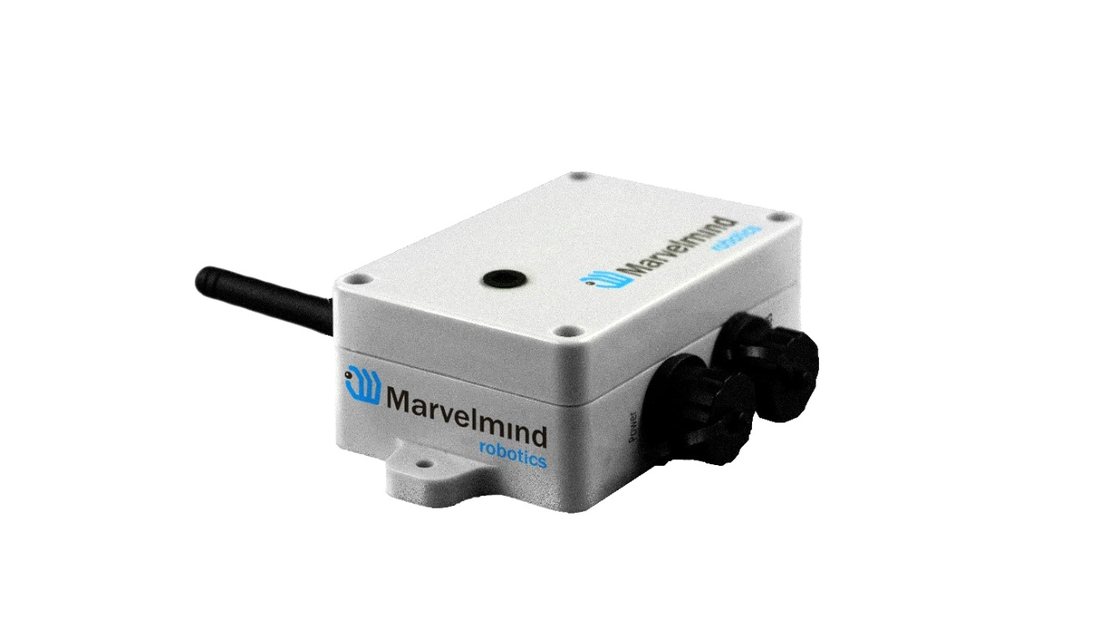
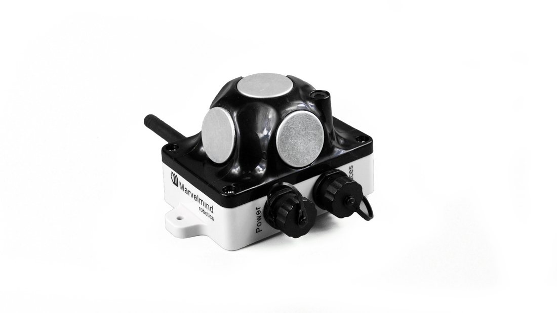
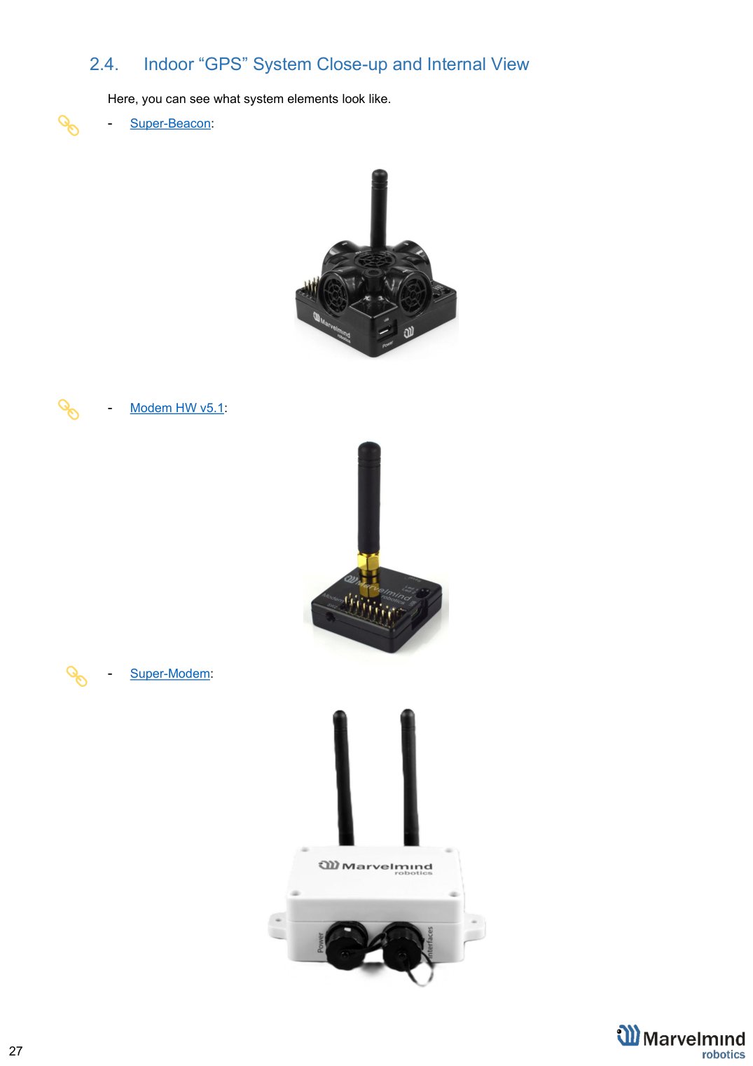
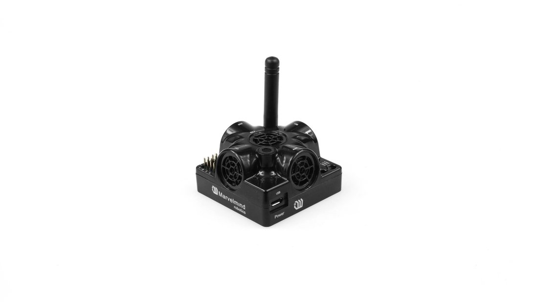
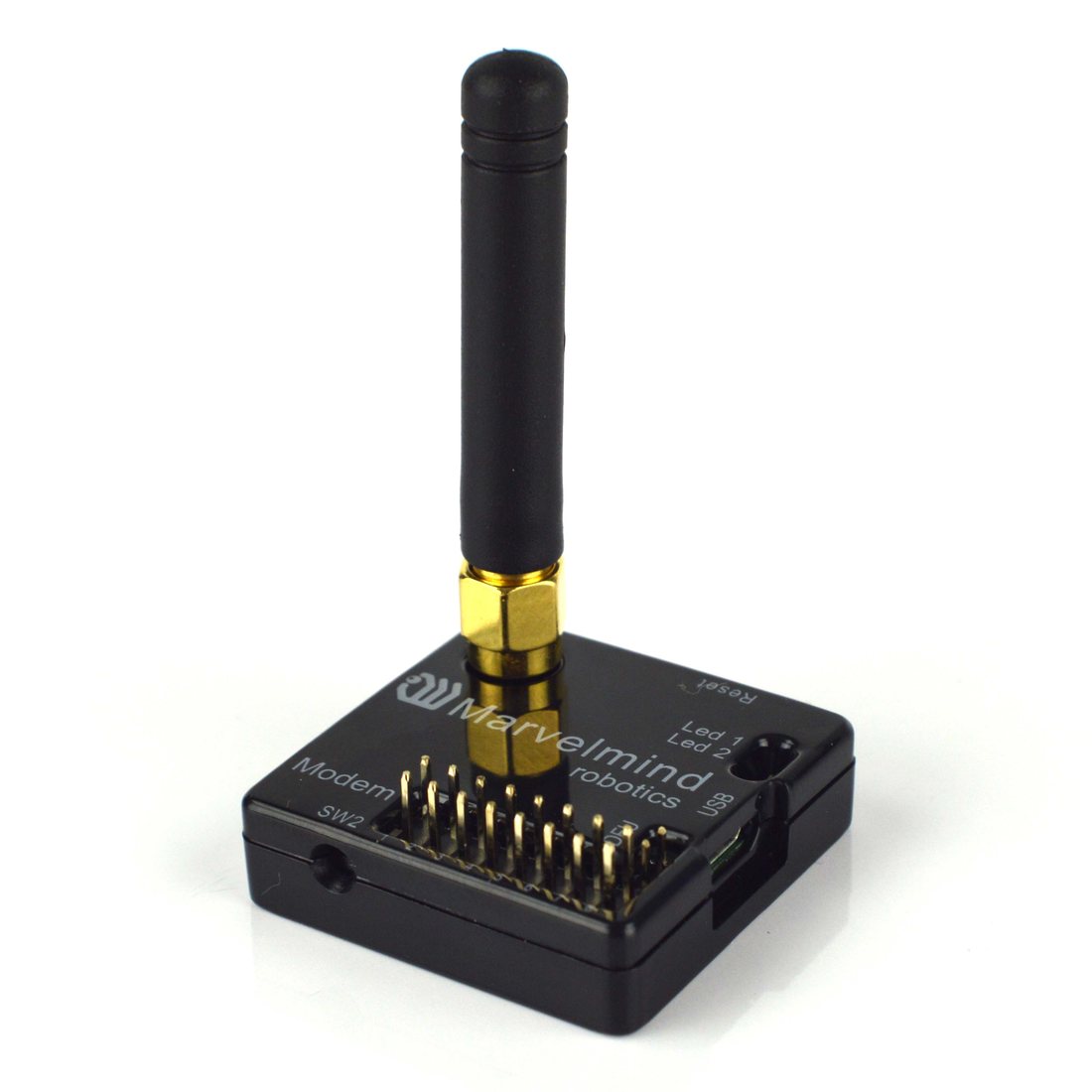
 Here, you can see what system elements look like.


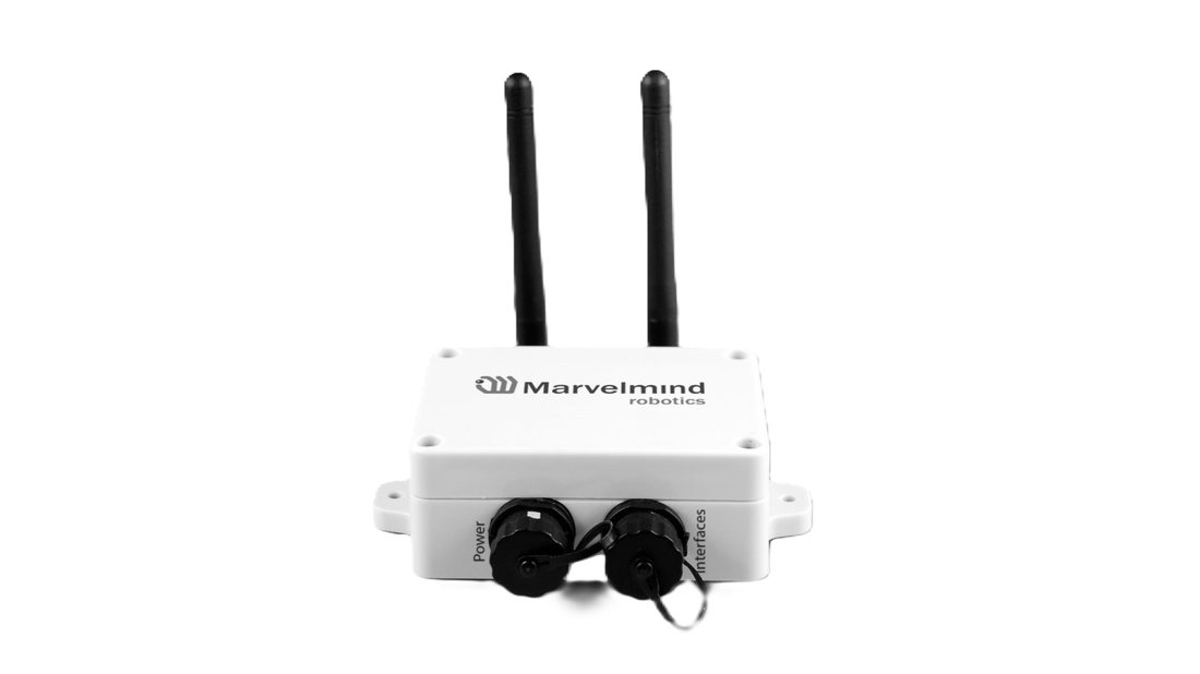


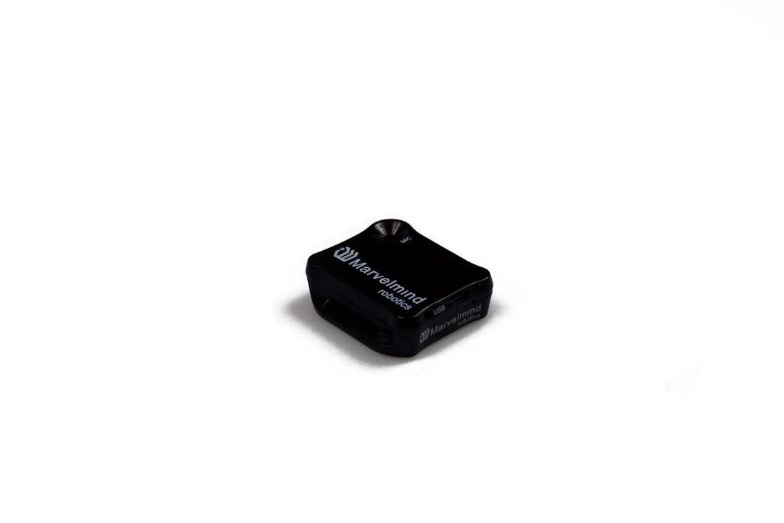
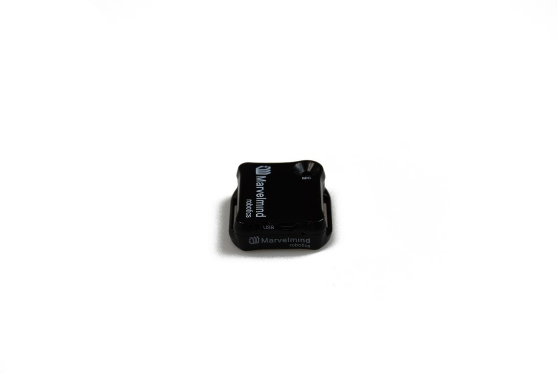

 Beacon Mini-TX:
 Beacon Industrial-RX:
- Industrial Super-Beacon Metal-25 kHz:
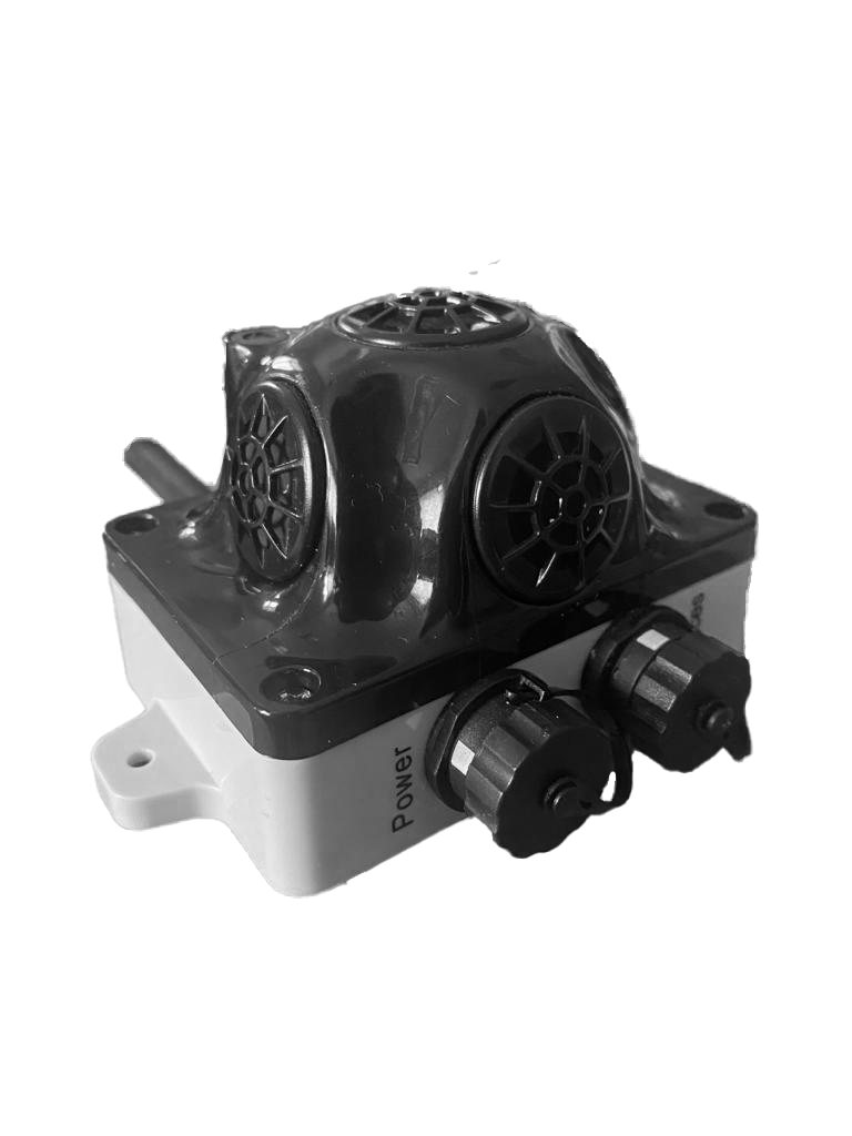
- Industrial Super-Beacon-Plastic: