
Interfaces and pinouts
This chapter as a clean, readable HTML page.
The “Interfaces and pinouts” chapter of the Operating Manual, reproduced as a real HTML page. Anything unclear? Open the original PDF of just this chapter (pages 239-243) (also pinned top-left). Hub: all chapters.
Indoor “GPS” system supports many external interfaces that can feed measured location data to an external system (robot, copter, VR, etc.).
There are two different ways to obtain the mobile beacons’ location data from the system:
- From the mobile beacons
- Each mobile beacon knows its position and does not know the positions of the other mobile beacons
- From modem
- Knows the position of every mobile beacon in the system
Data from the mobile beacons and the modem can be obtained simultaneously if necessary.
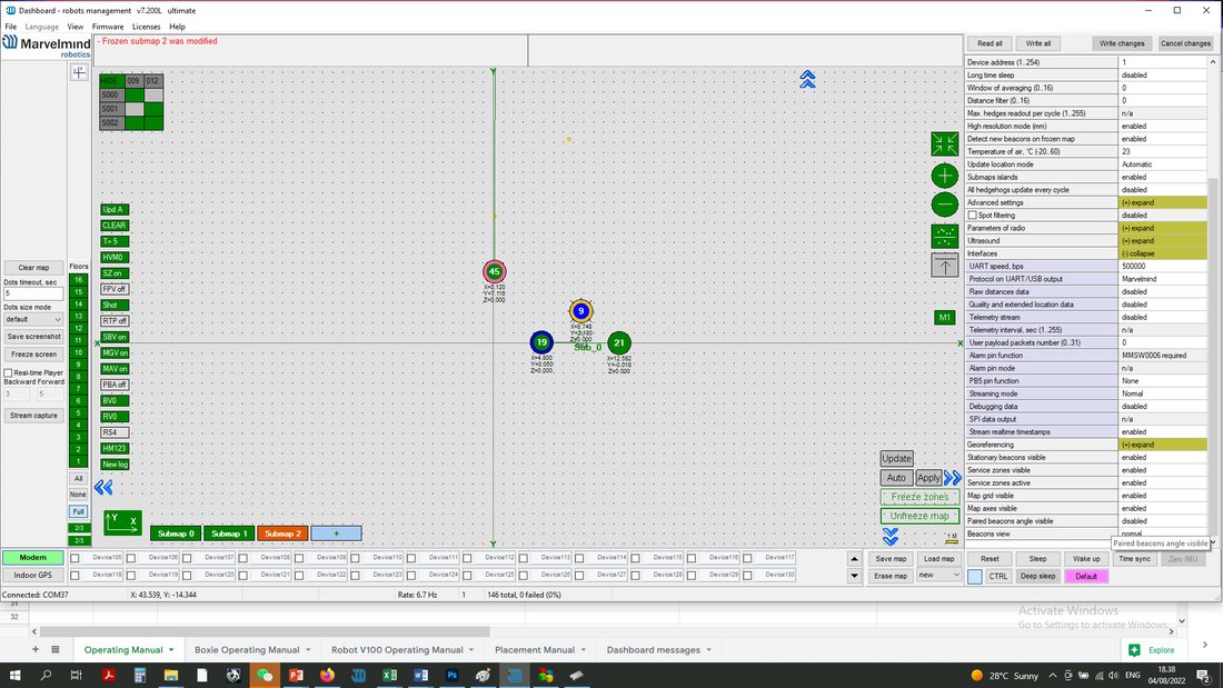
Starting from software version v7.200, real-time timestamps are enabled by default. If you need an old streaming format with local timestamps for compatibility with older software, you can disable this option in the device settings in the dashboard:
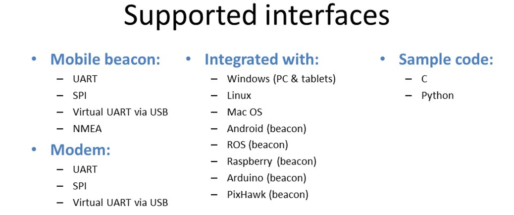
 A list of the supported interfaces is shown below.
 More information on the interfaces can be found here.
Super-Beacon External Interface Pinout Top View
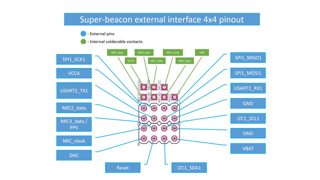 4×4 pinout for Super-Beacon:
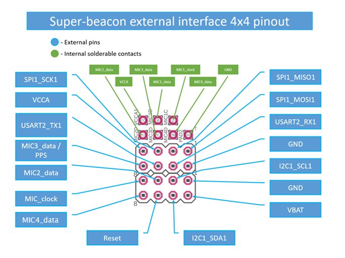 4×4 pinout for Super-Beacon-2, 3, 4:
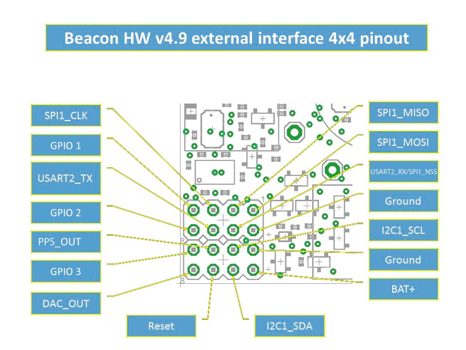 Beacon HW v4.9 External Interface 4×4 Pinout Top View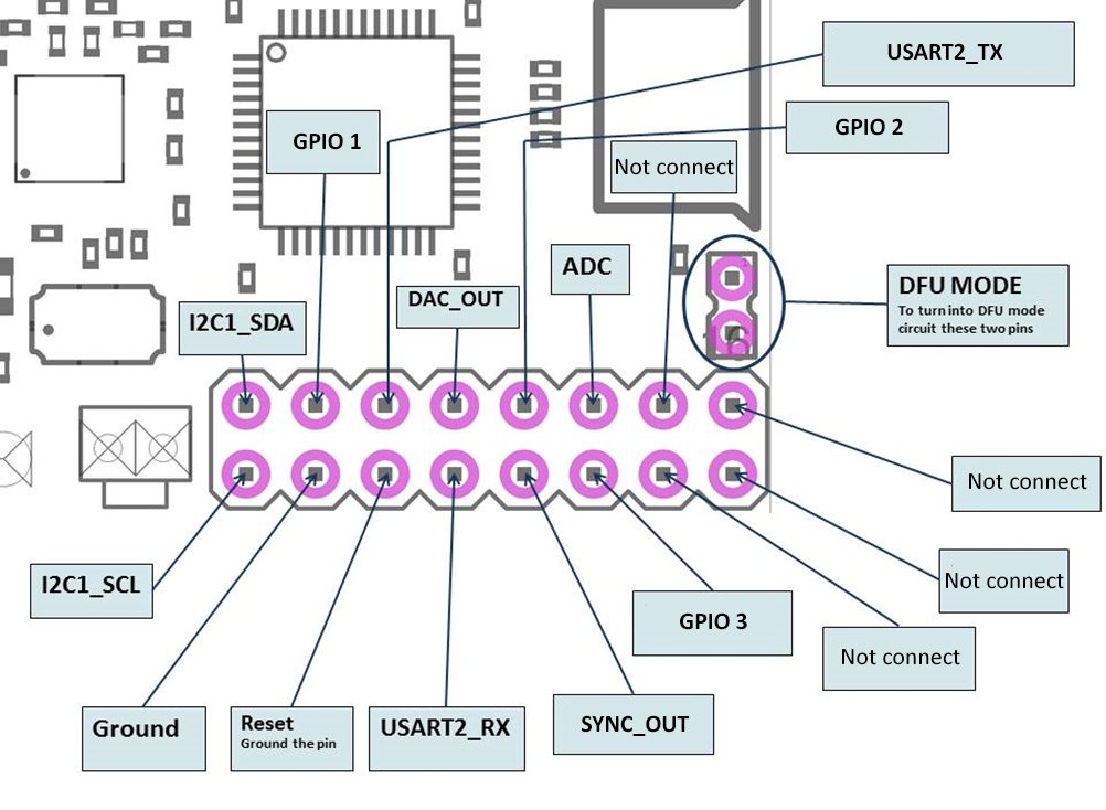
Mini-RX Internal Solderable Pinouts
 Use it only if you are sure that you can solder it correctly.
Do not forget to turn off the beacon with DIP switches.
If you solder badly and kill the beacon, the Marvelmind team won’t be responsible.
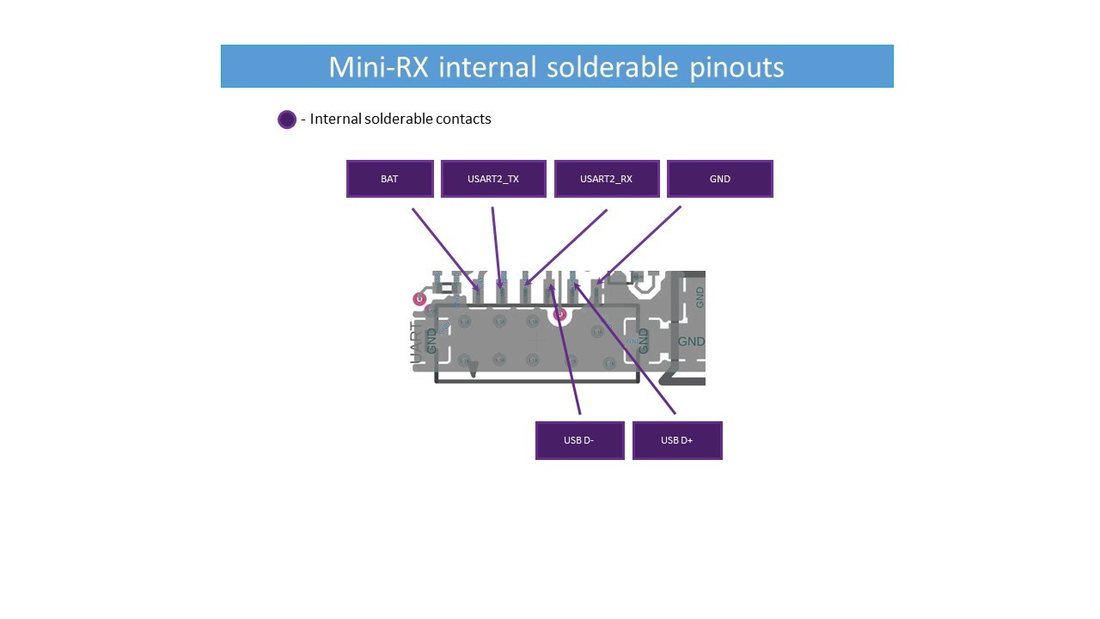 To get UART data streaming from beacon Mini-RX, you must solder to the pins on the board.
*BAT – you can disconnect the internal battery and supply here an external power source of 3.5 V-5.2 V to the point with a current up to 50 mA