Protocols via UART
This chapter as a clean, readable HTML page.
The “Protocols via UART” chapter of the Interfaces and Protocols, reproduced as a real HTML page. Anything unclear? Open the original PDF of just this chapter (pages 15-55) (also pinned top-left). Hub: all chapters.
‘Marvelmind’ protocol for streaming
All streaming packets have same general structure:
Offset | Size (bytes) | Type | Description | Value |
0 | 1 | uint8_t | Destination address | 0xff |
1 | 1 | uint8_t | Type of packet | 0x47 |
2 | 2 | uint16_t | Code of data in packet | See detail |
4 | 1 | uint8_t | Number of bytes of data transmitting | N |
5 | N | N bytes | Payload data according to code of data field | |
5+N | 2 | uint16_t | CRC-16 (see appendix 1) |
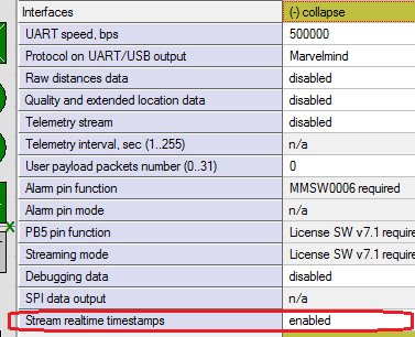
Starting from software version v7.200 real-time timestamps are enabled by default. This means that packets 0x0081, 0x0083, 0x0084, 0x0085 are streamed out instead of packets 0x0011, 0x0003, 0x0004, 0x0005 correspondingly.
If you need an old streaming format with local timestamps for compatibility with older software, you can disable this option in the device settings in the dashboard:
Packet of hedgehog coordinates
This packet is transmitted every time new coordinates are measured or failed to measure.
Packet with mm resolution coordinates of mobile beacon and real-time timestamps (firmware V7.200+)
Supported hardware:
Super-Beacon: supported
Industrial Super-Beacon: supported
Modem HW5.1: supported
Super-Modem: supported
Mini-RX (Badge, Helmet, etc.): supported with the UART cable
Mini-TX: not supported in the current HW version
Mini-TX-2: supported with the UART cable
Modem HW4.9: supported
Beacon HW4.9: supported
Beacon HW4.5: supported
Please see the note about timestamps.
Offset | Size (bytes) | Type | Description | Value |
0 | 1 | uint8_t | Destination address | 0xff |
1 | 1 | uint8_t | Type of packet | 0x47 |
2 | 2 | uint16_t | Code of data in packet | 0x0081 |
4 | 1 | uint8_t | Number of bytes of data transmitting | N |
5 | 8 | int64_t | Timestamp – Unix time – number of milliseconds from 1970.01.01 00:00:00. Time, synchronized by all devices with modem and dashboard. | |
13 | 4 | int32_t | Coordinate X of beacon, mm | |
17 | 4 | int32_t | Coordinate Y of beacon, mm | |
21 | 4 | int32_t | Coordinate Z, height of beacon, mm | |
25 | 1 | uint8_t | Byte of flags: Bit 0: 1 – coordinates unavailable. Data from fields X,Y,Z should not be used. Bit 1: timestamp units indicator (see note) Bit 2: 1 – user button is pushed (V5.23+) Bit 3: 1 – data are available for uploading to user device, see section 2 (V5.34+) Bit 4: 1 – want to download data from user device, see section 2 (V5.34+) Bit 5: 1 – second user button is pushed (V5.74+) Bit 6: 1 – data for another hedgehog (not same one that sending this packet) Bit 7: – 1 – out of geofencing zone | |
26 | 1 | uint8_t | Address of hedgehog | |
27 | 2 | uint16_t | Bit 0…11: orientation of hedgehogs pair in XY plane, decidegrees (0…3600) Bit 12: 1 – coordinates are given for center of beacons pair; 0 – coordinates for specified hedgehog Bit 13: 1 – orientation is not applicable Bit 14…15: reserved (0) | |
29 | 2 | uint16_t | Time passed from ultrasound emission to current time, milliseconds (V5.88+) | |
31 | M=N-26 | Optional data – see the list | ||
31+M | 2 | uint16_t | CRC-16 (see appendix 1) |
Optional data in mobile beacon location packet can include following structures:
- Speed data (7 bytes). Should be enabled in interfaces section of mobile beacon settings in the dashboard
Offset | Size (bytes) | Type | Description | Value |
0 | 1 | uint8_t | Code of data field = 1 means a vector of speed | 1 |
1 | 2 | int16_t | Speed along X, mm/sec | |
3 | 2 | int16_t | Speed along Y, mm/sec | |
5 | 2 | int16_t | Speed along Z, mm/sec |
Packet with cm resolution coordinates of mobile beacon
Obsolete packet, replaced by 0x0081. See details for the obsolete packet here.
Packet with mm resolution coordinates of mobile beacon
Obsolete packet, replaced by 0x0081. See details for the obsolete packet here.
Packet of stationary beacon’s coordinates
This packet is transmitted when the map is frozen, and repeats every 10 sec.
Packet with mm resolution coordinates of stationary beacons, code of data 0x0012 (firmware V5.35+)
Supported hardware:
Super-Beacon: supported
Industrial Super-Beacon: supported
Modem HW5.1: supported
Super-Modem: supported
Mini-RX (Badge, Helmet, etc.): supported with the UART cable
Mini-TX: not supported in the current HW version
Mini-TX-2: supported with the UART cable
Modem HW4.9: supported
Beacon HW4.9: supported
Beacon HW4.5: supported
Offset | Size (bytes) | Type | Description | Value |
0 | 1 | uint8_t | Address | 0xff |
1 | 1 | uint8_t | Type of packet | 0x47 |
2 | 2 | uint16_t | Code of data in packet | 0x0012 |
4 | 1 | uint8_t | Number of bytes of data transmitting | 1+N*14 |
5 | 1 | uint8_t | Number of beacons in packet | N |
6 | 1 | N*14 bytes | Data for N beacons | |
6+N*14 | 2 | uint16_t | CRC-16 (see appendix 1) |
Format of data structure for every of N beacons:
Offset | Size (bytes) | Type | Description |
0 | 1 | uint8_t | Address of beacon |
1 | 4 | int32_t | Coordinate X of beacon, mm |
5 | 4 | int32_t | Coordinate Y of beacon, mm |
9 | 4 | int32_t | Coordinate Z, height of beacon, mm |
13 | 1 | uint8_t | Bit 0: 1 = location not applicable Bit 1…7: reserved |
Packet with cm resolution coordinates of stationary beacons, code of data 0x0002.
Obsolete packet, replaced by 0x0012. See details for the obsolete packet here.
Packet of raw inertial sensors data
This packet is transmitted when new inertial sensors data available.
Packet of raw inertial sensors data with real-time timestamps, code of data 0x0083 (firmware V7.200+)
This packet is transmitted when new inertial sensors data available.
Supported hardware:
Super-Beacon: supported, 100 Hz (if ‘Raw inertial sensors data’ enabled)
Industrial Super-Beacon: supported, 100 Hz (if ‘Raw inertial sensors data’ enabled)
Modem HW5.1: supported, system update rate (if ‘IMU via modem’ enabled)
Super-Modem: supported, system update rate (if ‘IMU via modem’ enabled)
Mini-RX (Badge, Helmet, etc.): supported, 100 Hz (if ‘Raw inertial sensors data’ enabled)
with the UART cable
Mini-TX: not supported in the current HW version
Mini-TX-2: supported, 100 Hz (if ‘Raw inertial sensors data’ enabled)
Modem HW4.9: supported, system update rate (if ‘IMU via modem’ enabled)
Beacon HW4.9: supported, 100 Hz (if ‘Raw inertial sensors data’ enabled)
Beacon HW4.5: supported, 100 Hz (if ‘Raw inertial sensors data’ enabled)
Please see the note about timestamps.
Offset | Size (bytes) | Type | Description | Value |
0 | 1 | uint8_t | Address | 0xff |
1 | 1 | uint8_t | Type of packet | 0x47 |
2 | 2 | uint16_t | Code of data in packet | 0x0083 |
4 | 1 | uint8_t | Number of bytes of data transmitting | |
5 | 36 | Data packet (see lower) | ||
41 | 2 | uint16_t | CRC-16 (see appendix 1) |
Format of data packet
Offset | Size (bytes) | Type | Description | Value |
0 | 2 | int16_t | Accelerometer, X axis, 1 mg/LSB | |
2 | 2 | int16_t | Accelerometer, Y axis, 1 mg/LSB | |
4 | 2 | int16_t | Accelerometer, Z axis, 1 mg/LSB | |
6 | 2 | int16_t | Gyroscope, X axis, 0.0175 dps/LSB | |
8 | 2 | int16_t | Gyroscope, Y axis, 0.0175 dps/LSB | |
10 | 2 | int16_t | Gyroscope, Z axis, 0.0175 dps/LSB | |
12 | 2 | int16_t | Compass, X axis, 1100 LSB/Gauss | |
14 | 2 | int16_t | Compass, Y axis, 1100 LSB/Gauss | |
16 | 2 | int16_t | Compass, Z axis, 980 LSB/Gauss | |
18 | 1 | uint8_t | Address of beacon | |
19 | 5 | 5 bytes | Reserved (0) | |
24 | 8 | int64_t | Timestamp – Unix time – number of milliseconds from 1970.01.01 00:00:00. Time, synchronized by all devices with modem and dashboard. | |
32 | 1 | uint8_t | Flags: Bit 0: 1 = accelerometer data n/a Bit 1: 1 = Gyroscope data n/a Bit 2: 1 = Compass data n/a Bit 3…7 – reserved (0) | |
33 | 3 | 3 bytes | reserved |
Note: Compass data are available only for HW v4.9 beacons with IMU.
Packet of raw inertial sensors data, code of data 0x0003
Obsolete packet, replaced by 0x0083. See details for the obsolete packet here.
Packet of raw distances data Packet of raw distances data with real-time timestamps, code of data 0x0084 (firmware V7.200+)
This packet is transmitted every time new coordinates are measured or failed to measure, after the packet with coordinates of mobile beacon.
Available only if “raw distances data” option is enabled in ‘Interfaces’ section of settings.
Supported hardware:
Super-Beacon: supported
Industrial Super-Beacon: supported
Modem HW5.1: supported
Super-Modem: supported
Mini-RX (Badge, Helmet, etc.): supported with the UART cable
Mini-TX: not supported in the current HW version
Mini-TX-2: supported with the UART cable
Modem HW4.9: supported
Beacon HW4.9: supported
Beacon HW4.5: supported
Please see the note about timestamps.
Offset | Size (bytes) | Type | Description | Value |
0 | 1 | uint8_t | Address | 0xff |
1 | 1 | uint8_t | Type of packet | 0x47 |
2 | 2 | uint16_t | Code of data in packet | 0x0084 |
4 | 1 | uint8_t | Number of bytes of data transmitting | |
5 | 36 | Data packet (see lower) | ||
41 | 2 | uint16_t | CRC-16 (see appendix 1) |
Format of data packet
Offset | Size (bytes) | Type | Description | Value |
0 | 1 | uint8_t | Address of hedgehog | |
1 | 6 | Distance item 1 | ||
7 | 6 | Distance item 2 | ||
13 | 6 | Distance item 3 | ||
19 | 6 | Distance item 4 | ||
25 | 8 | int64_t | Timestamp – unix time of beacon ultrasound emission, number of milliseconds from 1970.01.01 00:00:00. Time, synchronized by all devices with modem and dashboard. | |
29 | 2 | uint16_t | Time passed from ultrasound emission to current time, milliseconds (V5.89+) | |
31 | 1 | uint8_t | reserved |
Format of distance item
Offset | Size (bytes) | Type | Description | Value |
0 | 1 | uint8_t | Address of beacon (0 if item not filled) | |
1 | 4 | uint32_t | Distance to the beacon, mm | |
5 | 1 | uint8_t | Bit 0: 1 = Distance not applicable Bit 1…7: Reserved (0) |
Packet of raw distances with candidates data with real-time timestamps, code of data 0x0094 (firmware V8.431+)
This packet is transmitted every time new coordinates are measured or failed to measure, after the packet with coordinates of mobile beacon.
Available only if “extra raw distances data” option is enabled in ‘Interfaces’ section of settings.
Supported hardware:
Super-Beacon: supported
Industrial Super-Beacon: supported
Modem HW5.1: on demand
Super-Modem: on demand
Mini-RX (Badge, Helmet, etc.): supported with the UART cable
Mini-TX: not supported
Mini-TX-2: on demand
Modem HW4.9: not supported
Beacon HW4.9: not supported
Beacon HW4.5: not supported
Please see the note about timestamps.
Offset | Size (bytes) | Type | Description | Value |
0 | 1 | uint8_t | Address | 0xff |
1 | 1 | uint8_t | Type of packet | 0x47 |
2 | 2 | uint16_t | Code of data in packet | 0x0094 |
4 | 1 | uint8_t | Number of bytes of data transmitting | |
5 | 80 | Data packet (see lower) | ||
85 | 2 | uint16_t | CRC-16 (see appendix 1) |
Format of data packet
Offset | Size (bytes) | Type | Description | Value |
0 | 1 | uint8_t | Address of hedgehog | |
1 | 17 | Distance item 1 | ||
18 | 17 | Distance item 2 | ||
35 | 17 | Distance item 3 | ||
52 | 17 | Distance item 4 | ||
69 | 8 | int64_t | Timestamp – unix time of beacon ultrasound emission, number of milliseconds from 1970.01.01 00:00:00. Time, synchronized by all devices with modem and dashboard. | |
77 | 2 | uint16_t | Time passed from ultrasound emission to current time, milliseconds (V5.89+) | |
79 | 1 | uint8_t | reserved |
Format of distance item
Offset | Size (bytes) | Type | Description | Value |
0 | 1 | uint8_t | Address of beacon (0 if item not filled) | |
1 | 1 | uint8_t | Number of distance candidates | |
2 | 4 | uint32_t | First candidate of distance to the beacon, mm | |
6 | 1 | uint8_t | Quality of first candidate, % | |
7 | 4 | uint32_t | Second candidate of distance to the beacon, mm | |
11 | 1 | uint8_t | Quality of second candidate, % | |
12 | 4 | uint32_t | Third candidate of distance to the beacon, mm | |
16 | 1 | uint8_t | Quality of third candidate, % |
Packet of raw distances data, code of data 0x0004
Obsolete packet, replaced by 0x0084. See details for the obsolete packet here.
Packet of processed IMU data
This packet is transmitted when new inertial sensors data available.
Packet of processed IMU data with real-time timestamps, code of data 0x0085 (firmware V7.200+)
This packet is transmitted when new inertial sensors data available.
Supported hardware:
Super-Beacon: supported, 100 Hz (if ‘Processed IMU data’ enabled)
Industrial Super-Beacon: supported, 100 Hz (if ‘Processed IMU data’ enabled)
Modem HW5.1: supported, system update rate (if ‘IMU via modem’ enabled)
Super-Modem: supported, system update rate (if ‘IMU via modem’ enabled)
Mini-RX (Badge, Helmet, etc.): supported, 100 Hz (if ‘Processed IMU data’ enabled)
with the UART cable for Mini-Rx
Mini-TX: not supported in the current HW version
Mini-TX-2: supported, 100 Hz (if ‘Processed IMU data’ enabled)
Modem HW4.9: supported, system update rate (if ‘IMU via modem’ enabled)
Beacon HW4.9: supported, 100 Hz (if ‘Processed IMU data’ enabled)
Beacon HW4.5: supported, 100 Hz (if Processed IMU data’ enabled)
Please see the note about timestamps.
Offset | Size (bytes) | Type | Description | Value |
0 | 1 | uint8_t | Address | 0xff |
1 | 1 | uint8_t | Type of packet | 0x47 |
2 | 2 | uint16_t | Code of data in packet | 0x0085 |
4 | 1 | uint8_t | Number of bytes of data transmitting | |
5 | 46 | Data packet (see lower) | ||
51 | 2 | uint16_t | CRC-16 (see appendix 1) |
Format of data packet
Offset | Size (bytes) | Type | Description | Value |
0 | 4 | int32_t | Coordinate X of beacon (fusion), mm | |
4 | 4 | int32_t | Coordinate Y of beacon (fusion), mm | |
8 | 4 | int32_t | Coordinate Z of beacon (fusion), mm | |
12 | 2 | int16_t | W field of rotation quaternion (angles) | |
14 | 2 | int16_t | X field of rotation quaternion (angles) | |
16 | 2 | int16_t | Y field of rotation quaternion (angles) | |
18 | 2 | int16_t | Z field of rotation quaternion (angles) | |
20 | 2 | int16_t | Velocity X of beacon (fusion), mm/s | |
22 | 2 | int16_t | Velocity Y of beacon (fusion), mm/s | |
24 | 2 | int16_t | Velocity Z of beacon (fusion), mm/s | |
26 | 2 | int16_t | Acceleration X of beacon, mm/s2 | |
28 | 2 | int16_t | Acceleration Y of beacon, mm/s2 | |
30 | 2 | int16_t | Acceleration Z of beacon, mm/s2 | |
32 | 1 | uint8_t | Address of beacon | |
33 | 1 | 1 byte | Reserved (0) | |
34 | 8 | int64_t | Timestamp – Unix time – number of milliseconds from 1970.01.01 00:00:00. Time, synchronized by all devices with modem and dashboard. | |
42 | 1 | uint8_t | Flags: Bit 0: 1 = Location data n/a Bit 1: 1 = Quaternion data n/a Bit 2: 1 = Velocity data n/a Bit 3: 1 = Acceleration data n/a | |
43 | 3 | 3 bytes | Reserved (0) |
Note: Quaternion is normalized to 10000 value.
Packet of processed IMU data, code of data 0x0005
Obsolete packet, replaced by 0x0085. See details for the obsolete packet here.
Packet of telemetry data (code of data 0x0006)
This packet is transmitted after location update, if the option “Telemetry stream” is enabled in ‘Interfaces’ section of settings.
Supported hardware:
Super-Beacon: supported
Industrial Super-Beacon: supported
Modem HW5.1: supported (firmware V7.000+)
Super-Modem: supported (firmware V7.000+)
Mini-RX (Badge, Helmet, etc.): supported with the UART cable
Mini-TX: not supported in the current HW version
Mini-TX-2: supported with the UART cable
Modem HW4.9: not supported
Beacon HW4.9: supported
Beacon HW4.5: supported
Offset | Size (bytes) | Type | Description | Value |
0 | 1 | uint8_t | Address | 0xff |
1 | 1 | uint8_t | Type of packet | 0x47 |
2 | 2 | uint16_t | Code of data in packet | 0x0006 |
4 | 1 | uint8_t | Number of bytes of data transmitting | |
5 | 16 | Data packet (see lower) | ||
21 | 2 | uint16_t | CRC-16 (see appendix 1) |
Format of data packet
Offset | Size (bytes) | Type | Description | Value |
0 | 2 | uint16_t | Battery voltage, mV | |
2 | 1 | int8_t | RSSI, dBm | |
3 | 1 | uint8_t | Address of the beacon | |
4 | 12 | Reserved (0) |
Packet of quality and extended location data (code of data 0x0007)
This packet is transmitted after location update, if the option “Quality and extended location data” is enabled in ‘Interfaces’ section of settings.
Supported hardware:
Super-Beacon: supported
Industrial Super-Beacon: supported
Modem HW5.1: supported
Super-Modem: supported
Mini-RX (Badge, Helmet, etc.): supported with the UART cable
Mini-TX: not supported in the current HW version
Mini-TX-2: supported with the UART cable
Modem HW4.9: supported (only quality field)
Beacon HW4.9: supported (only quality field)
Beacon HW4.5: supported (only quality field)
Offset | Size (bytes) | Type | Description | Value |
0 | 1 | uint8_t | Address | 0xff |
1 | 1 | uint8_t | Type of packet | 0x47 |
2 | 2 | uint16_t | Code of data in packet | 0x0007 |
4 | 1 | uint8_t | Number of bytes of data transmitting | |
5 | 16 | Data packet (see lower) | ||
21 | 2 | uint16_t | CRC-16 (see appendix 1) |
Format of data packet
Offset | Size (bytes) | Type | Description | Value |
0 | 1 | uint8_t | Device address | |
1 | 1 | uint8_t | Positioning quality, % | |
2 | 1 | uint8_t | 0 = no geofencing zone alarm 1…255 – index of geofencing zone This field requires MMSW0005 license. | |
3 | 13 | Reserved (0) |
Retired features
Here described obsolete packets, used in old version of software and replaced by default by other packets.
Packet with cm resolution coordinates of mobile beacon
Obsolete packet. Replaced by 0x0081.
Supported hardware:
Super-Beacon: supported
Industrial Super-Beacon: supported
Modem HW5.1: supported
Super-Modem: supported
Mini-RX (Badge, Helmet, etc.): supported with the UART cable
Mini-TX: not supported in the current HW version
Mini-TX-2: supported with the UART cable
Modem HW4.9: supported
Beacon HW4.9: supported
Beacon HW4.5: supported
Offset | Size (bytes) | Type | Description | Value |
0 | 1 | uint8_t | Destination address | 0xff |
1 | 1 | uint8_t | Type of packet | 0x47 |
2 | 2 | uint16_t | Code of data in packet | 0x0001 |
4 | 1 | uint8_t | Number of bytes of data transmitting | 0x10 |
5 | 4 | uint32_t | Timestamp – internal time of beacon ultrasound emission, in milliseconds from the moment of the latest wakeup event. See note. | |
9 | 2 | int16_t | Coordinate X of beacon, cm | |
11 | 2 | int16_t | Coordinate Y of beacon, cm | |
13 | 2 | int16_t | Coordinate Z, height of beacon, cm | |
15 | 1 | uint8_t | Byte of flags: Bit 0: 1 – coordinates unavailable. Data from fields X, Y, Z should not be used. Bit 1: timestamp units indicator (see note) Bit 2: 1 – user button is pushed (V5.23+) Bit 3: 1 – data are available for uploading to user device, see section 2 (V5.34+) Bit 4: 1 – want to download data from user device, see section 2 (V5.34+) Bit 5: 1 – second user button is pushed (V5.74+) Bit 6: 1 – data for another hedgehog (not same one that sending this packet) Bit 7: – reserved (0) | |
16 | 1 | uint8_t | Address of hedgehog | |
17 | 2 | uint16_t | Bit 0…11: orientation of hedgehogs pair in XY plane, decidegrees (0…3600) Bit 12: 1 – coordinates are given for center of beacons pair; 0 – coordinates for specified beacon Bit 13: 1 – orientation is not applicable Bit 14…15: reserved (0) | |
19 | 2 | uint16_t | Time passed from ultrasound emission to current time, milliseconds (V5.88+) | |
21 | 2 | uint16_t | CRC-16 (see appendix 1) |
Packet with mm resolution coordinates of mobile beacon
Obsolete packet. Replaced by 0x0081.
Supported hardware:
Super-Beacon: supported
Industrial Super-Beacon: supported
Modem HW5.1: supported
Super-Modem: supported
Mini-Rx (Badge, Helmet, etc.): supported with the UART cable
Mini-TX: not supported in the current HW version
Mini-TX-2: supported with the UART cable
Modem HW4.9: supported
Beacon HW4.9: supported
Beacon HW4.5: supported
Please see the note about timestamps.
Offset | Size (bytes) | Type | Description | Value |
0 | 1 | uint8_t | Destination address | 0xff |
1 | 1 | uint8_t | Type of packet | 0x47 |
2 | 2 | uint16_t | Code of data in packet | 0x0011 |
4 | 1 | uint8_t | Number of bytes of data transmitting | N |
5 | 4 | uint32_t | Timestamp – internal time of beacon ultrasound emission, in milliseconds from the moment of the latest wakeup event. See note. | |
9 | 4 | int32_t | Coordinate X of beacon, mm | |
13 | 4 | int32_t | Coordinate Y of beacon, mm | |
17 | 4 | int32_t | Coordinate Z, height of beacon, mm | |
21 | 1 | uint8_t | Byte of flags: Bit 0: 1 – coordinates unavailable. Data from fields X,Y,Z should not be used. Bit 1: timestamp units indicator (see note) Bit 2: 1 – user button is pushed (V5.23+) Bit 3: 1 – data are available for uploading to user device, see section 2 (V5.34+) Bit 4: 1 – want to download data from user device, see section 2 (V5.34+) Bit 5: 1 – second user button is pushed (V5.74+) Bit 6: 1 – data for another hedgehog (not same one that sending this packet) Bit 7: – 1 – out of geofencing zone | |
22 | 1 | uint8_t | Address of hedgehog | |
23 | 2 | uint16_t | Bit 0…11: orientation of hedgehogs pair in XY plane, decidegrees (0…3600) Bit 12: 1 – coordinates are given for center of beacons pair; 0 – coordinates for specified hedgehog Bit 13: 1 – orientation is not applicable Bit 14…15: reserved (0) | |
25 | 2 | uint16_t | Time passed from ultrasound emission to current time, milliseconds (V5.88+) | |
27 | M= N-22 | Optional data – see the list | ||
27+M | 2 | uint16_t | CRC-16 (see appendix 1) |
Note: for firmware versions before V5.20 timestamp is in 1/64 sec units and timestamp units indicator (bit 1 of flags byte) is 0. For versions 5.20 and higher timestamp is in milliseconds and timestamp units indicator is 1.
Packet with cm resolution coordinates of stationary beacons, code of data 0x0002.
Obsolete packet. Replaced by 0x0012.
Supported hardware:
Super-Beacon: supported
Industrial Super-Beacon: supported
Modem HW5.1: supported
Super-Modem: supported
Mini-RX (Badge, Helmet, etc.): supported with the UART cable
Mini-TX: not supported in the current HW version
Mini-TX-2: supported with the UART cable
Modem HW4.9: supported
Beacon HW4.9: supported
Beacon HW4.5: supported
Offset | Size (bytes) | Type | Description | Value |
0 | 1 | uint8_t | Address | 0xff |
1 | 1 | uint8_t | Type of packet | 0x47 |
2 | 2 | uint16_t | Code of data in packet | 0x0002 |
4 | 1 | uint8_t | Number of bytes of data transmitting | 1+N*8 |
5 | 1 | uint8_t | Number of beacons in packet | N |
6 | 1 | N*8 bytes | Data for N beacons | |
6+N*8 | 2 | uint16_t | CRC-16 (see appendix 1) |
Format of data structure for every of N beacons:
Offset | Size (bytes) | Type | Description |
0 | 1 | uint8_t | Address of beacon |
1 | 2 | int16_t | Coordinate X of beacon, cm |
3 | 2 | int16_t | Coordinate Y of beacon, cm |
5 | 2 | int16_t | Coordinate Z, height of beacon, cm |
7 | 1 | uint8_t | Reserved (0) |
Packet of raw inertial sensors data, code of data 0x0003
Obsolete packet. Replaced by 0x0083.
Supported hardware:
Super-Beacon: supported, 100 Hz (if ‘Raw inertial sensors data’ enabled)
Industrial Super-Beacon: supported, 100 Hz (if ‘Raw inertial sensors data’ enabled)
Modem HW5.1: supported, system update rate (if ‘IMU via modem’ enabled)
Super-Modem: supported, system update rate (if ‘IMU via modem’ enabled)
Mini-RX (Badge, Helmet, etc.): supported, 100 Hz (if ‘Raw inertial sensors data’ enabled)
with the UART cable
Mini-TX: not supported in the current HW version
Mini-TX-2: supported, 100 Hz (if ‘Raw inertial sensors data’ enabled)
Modem HW4.9: supported, system update rate (if ‘IMU via modem’ enabled)
Beacon HW4.9: supported, 100 Hz (if ‘Raw inertial sensors data’ enabled)
Beacon HW4.5: supported, 100 Hz (if ‘Raw inertial sensors data’ enabled)
Please see the note about timestamps.
Offset | Size (bytes) | Type | Description | Value |
0 | 1 | uint8_t | Address | 0xff |
1 | 1 | uint8_t | Type of packet | 0x47 |
2 | 2 | uint16_t | Code of data in packet | 0x0003 |
4 | 1 | uint8_t | Number of bytes of data transmitting | |
5 | 32 | Data packet (see lower) | ||
37 | 2 | uint16_t | CRC-16 (see appendix 1) |
Format of data packet
Offset | Size (bytes) | Type | Description | Value |
0 | 2 | int16_t | Accelerometer, X axis, 1 mg/LSB | |
2 | 2 | int16_t | Accelerometer, Y axis, 1 mg/LSB | |
4 | 2 | int16_t | Accelerometer, Z axis, 1 mg/LSB | |
6 | 2 | int16_t | Gyroscope, X axis, 0.0175 dps/LSB | |
8 | 2 | int16_t | Gyroscope, Y axis, 0.0175 dps/LSB | |
10 | 2 | int16_t | Gyroscope, Z axis, 0.0175 dps/LSB | |
12 | 2 | int16_t | Compass, X axis, 1100 LSB/Gauss | |
14 | 2 | int16_t | Compass, Y axis, 1100 LSB/Gauss | |
16 | 2 | int16_t | Compass, Z axis, 980 LSB/Gauss | |
18 | 1 | uint8_t | Address of beacon | |
19 | 5 | 5 bytes | Reserved (0) | |
24 | 4 | uint32_t | Timestamp, ms | |
28 | 1 | uint8_t | Flags: Bit 0: 1 = accelerometer data n/a Bit 1: 1 = Gyroscope data n/a Bit 2: 1 = Compass data n/a Bit 3…7 – reserved (0) | |
29 | 3 | 3 bytes | reserved |
Note: Compass data are available only for HW v4.9 beacons with IMU.
Packet of raw distances data, code of data 0x0004
Obsolete packet. Replaced by 0x0084.
Supported hardware:
Super-Beacon: supported
Industrial Super-Beacon: supported
Modem HW5.1: supported
Super-Modem: supported
Mini-RX (Badge, Helmet, etc.): supported with the UART cable
Mini-TX: not supported in the current HW version
Mini-TX-2: supported with the UART cable
Modem HW4.9: supported
Beacon HW4.9: supported
Beacon HW4.5: supported
Please see the note about timestamps.
Offset | Size (bytes) | Type | Description | Value |
0 | 1 | uint8_t | Address | 0xff |
1 | 1 | uint8_t | Type of packet | 0x47 |
2 | 2 | uint16_t | Code of data in packet | 0x0004 |
4 | 1 | uint8_t | Number of bytes of data transmitting | |
5 | 32 | Data packet (see lower) | ||
37 | 2 | uint16_t | CRC-16 (see appendix 1) |
Format of data packet
Offset | Size (bytes) | Type | Description | Value |
0 | 1 | uint8_t | Address of hedgehog | |
1 | 6 | Distance item 1 | ||
7 | 6 | Distance item 2 | ||
13 | 6 | Distance item 3 | ||
19 | 6 | Distance item 4 | ||
25 | 4 | uint32_t | Timestamp – internal time of beacon ultrasound emission, in milliseconds from the moment of the latest wakeup event (V5.89+). | |
29 | 2 | uint16_t | Time passed from ultrasound emission to current time, milliseconds (V5.89+) | |
31 | 1 | uint8_t | reserved |
Format of distance item
Offset | Size (bytes) | Type | Description | Value |
0 | 1 | uint8_t | Address of beacon (0 if item not filled) | |
1 | 4 | uint32_t | Distance to the beacon, mm | |
5 | 1 | uint8_t | Bit 0: 1 = Distance not applicable Bit 1…7: Reserved (0) |
Packet of processed IMU data, code of data 0x0005
Obsolete packet. Replaced by 0x0085.
Supported hardware:
Super-Beacon: supported angles, 100 Hz (if ‘Processed IMU data’ enabled)
Industrial Super-Beacon: supported angles, 100 Hz (if ‘Processed IMU data’ enabled)
Modem HW5.1: supported, system update rate (if ‘IMU via modem’ enabled)
Super-Modem: supported, system update rate (if ‘IMU via modem’ enabled)
Mini-RX (Badge, etc.): supported angles, 100 Hz (if ‘Processed IMU data’ enabled)
with the UART cable for Mini-Rx
Mini-TX: not supported in the current HW version
Mini-TX-2: supported angles, 100 Hz (if ‘Processed IMU data’ enabled)
Modem HW4.9: supported, system update rate (if ‘IMU via modem’ enabled)
Beacon HW4.9: supported, 100 Hz (if ‘Processed IMU data’ enabled)
Beacon HW4.5: supported, 100 Hz (if Processed IMU data’ enabled)
Please see the note about timestamps.
Offset | Size (bytes) | Type | Description | Value |
0 | 1 | uint8_t | Address | 0xff |
1 | 1 | uint8_t | Type of packet | 0x47 |
2 | 2 | uint16_t | Code of data in packet | 0x0005 |
4 | 1 | uint8_t | Number of bytes of data transmitting | |
5 | 42 | Data packet (see lower) | ||
47 | 2 | uint16_t | CRC-16 (see appendix 1) |
Format of data packet
Offset | Size (bytes) | Type | Description | Value |
0 | 4 | int32_t | Coordinate X of beacon (fusion), mm | |
4 | 4 | int32_t | Coordinate Y of beacon (fusion), mm | |
8 | 4 | int32_t | Coordinate Z of beacon (fusion), mm | |
12 | 2 | int16_t | W field of rotation quaternion (angles) | |
14 | 2 | int16_t | X field of rotation quaternion (angles) | |
16 | 2 | int16_t | Y field of rotation quaternion (angles) | |
18 | 2 | int16_t | Z field of rotation quaternion (angles) | |
20 | 2 | int16_t | Velocity X of beacon (fusion), mm/s | |
22 | 2 | int16_t | Velocity Y of beacon (fusion), mm/s | |
24 | 2 | int16_t | Velocity Z of beacon (fusion), mm/s | |
26 | 2 | int16_t | Acceleration X of beacon, mm/s2 | |
28 | 2 | int16_t | Acceleration Y of beacon, mm/s2 | |
30 | 2 | int16_t | Acceleration Z of beacon, mm/s2 | |
32 | 1 | uint8_t | Address of beacon | |
33 | 1 | 1 byte | Reserved (0) | |
34 | 4 | uint32_t | Timestamp, ms | |
38 | 1 | uint8_t | Flags: Bit 0: 1 = Location data n/a Bit 1: 1 = Quaternion data n/a Bit 2: 1 = Velocity data n/a Bit 3: 1 = Acceleration data n/a Bit 4…7 – reserved (0) | |
39 | 3 | 3 bytes | Reserved (0) |
Note: Quaternion is normalized to 10000 value
Protocol of reading/writing data from/to user device
Sending data from user device
Supported hardware:
Super-Beacon: supported
Industrial Super-Beacon: supported
Modem HW5.1: supported
Super-Modem: supported
Mini-RX (Badge, Helmet, etc.): supported with the UART cable
Mini-TX: not supported in the current HW version
Mini-TX-2: supported with the UART cable
Modem HW4.9: not supported
Beacon HW4.9: supported
Beacon HW4.5: supported
If the user device needs to transmit data via Marvelmind system, it should send following frame:
Offset | Size (bytes) | Type | Description | Value |
0 | 1 | uint8_t | Destination address | 0x00 |
1 | 1 | uint8_t | Type of packet | 0x49 |
2 | 2 | uint16_t | Code of data in packet | 0x0200 |
4 | 1 | uint8_t | Number of bytes of data transmitting | N |
5 | N | N bytes | Payload data | |
5+N | 2 | uint16_t | CRC-16 (see appendix 1) |
The data will be transmitted via radio to the modem by the parts of the size defined as ‘User payload data size’ in ‘Interfaces’ section of dashboard settings for hedgehog. The rate of sending these parts is equal to update rate of hedgehog. Buffer size in hedgehog is 128 bytes. Take this in attention to avoid overflow the buffer.
Writing data to user device
This packet is transmitted from Marvelmind device (modem or mobile beacon) to user device.
Offset | Size (bytes) | Type | Description | Value |
0 | 1 | uint8_t | Destination address | 0xff |
1 | 1 | uint8_t | Type of packet | 0x4a |
2 | 2 | uint16_t | Code of data in packet | 0x0200… 0x02ff |
4 | 1 | uint8_t | Number of bytes of data transmitting | N |
5 | N | N bytes | Payload data | |
5+N | 2 | uint16_t | CRC-16 (see appendix 1) |
For this command the codes of data from 0x200 to 0x2ff are reserved.
If the user device successfully processed the request, it should send a response in following format:
Offset | Size (bytes) | Type | Description | Value |
0 | 1 | uint8_t | Address of hedgehog (can get from 0x0001 or 0x0011 packet of streaming) | |
1 | 1 | uint8_t | Type of packet | 0x4a |
2 | 2 | uint16_t | Code of data in packet | 0x0200… 0x02ff |
4 | 2 | uint16_t | CRC-16 (see appendix 1) |
If the user device failed to process the request, it sends response in following format:
Offset | Size (bytes) | Type | Description | Value |
0 | 1 | uint8_t | Address of hedgehog (get from 0x0001 packet of streaming) | |
1 | 1 | uint8_t | Type of packet | 0xca |
2 | 2 | uint16_t | Code of requested data | 0x0200… 0x02ff |
4 | 1 | uint8_t | Code of error (see note) | 1 |
5 | 2 | uint16_t | CRC-16 (see appendix 1) |
In the following sections described the specific data writing requests.
Note: If user device could not process request from hedgehog, it should send reply with one of following error codes:
1 – unknown field "type of packet" in request
2 – unknown field "code of data" in request
3 – incorrect payload data in request
6 – device is busy and cannot retrieve requested data now
Request of writing the movement path
Supported hardware:
Super-Beacon: supported
Industrial Super-Beacon: supported
Modem HW5.1: on demand
Super-Modem: on demand
Mini-RX (Badge, Helmet, etc.): supported with the UART cable
Mini-TX: not supported in the current HW version
Mini-TX-2: supported with the UART cable
Modem HW4.9: not supported
Beacon HW4.9: supported
Beacon HW4.5: supported
This packet contains one command of elementary movement. The Marvelmind device sends one after another all commands for elementary movements in the path.
Offset | Size (bytes) | Type | Description | Value |
0 | 1 | uint8_t | Destination address | 0xff |
1 | 1 | uint8_t | Type of packet | 0x4a |
2 | 2 | uint16_t | Code of data in packet | 0x201 |
4 | 1 | uint8_t | Number of bytes of data transmitting | 0x0c |
5 | 12 | 12 bytes | Payload data | |
17 | 2 | uint16_t | CRC-16 (see appendix 1) |
Format of payload data:
Offset | Size (bytes) | Type | Description | Value |
0 | 1 | uint8_t | Type of elementary movement: 0 – move forward 1 – move backward 2 – rotate right (clockwise) 3 – rotate left (counterclockwise) 4 – pause 5 – repeat program from start 6 – move to specified point 7 – setup speed | |
1 | 1 | uint8_t | Index of this elementary movement (0 is the first) | |
2 | 1 | uint8_t | Total number of elementary movements | |
3 | 2 | int16_t | Parameter of movement: Types 0; 1 – distance of movement, cm Types 2; 3 – angle of rotation, degrees Type 4: time of pause, ms Type 6: X target coordinate, cm Type 7: speed, % | |
5 | 2 | int16_t | Parameter of movement: Type 6: Y target coordinate, cm | |
7 | 2 | int16_t | Parameter of movement: Type 6: Z target coordinate, cm | |
9 | 3 | 3 bytes | Reserved (0) |
Request of writing zones
Supported hardware:
Super-Beacon: supported
Industrial Super-Beacon: supported
Modem HW5.1: on demand
Super-Modem: on demand
Mini-RX (Badge, Helmet, etc.): supported with the UART cable
Mini-TX: not supported in the current HW version
Mini-TX-2: supported with the UART cable
Modem HW4.9: not supported
Beacon HW4.9: supported
Beacon HW4.5: supported
This packet contains one item of sequence of zones list. The Marvelmind device sends one after another all commands for zones list.
Offset | Size (bytes) | Type | Description | Value |
0 | 1 | uint8_t | Destination address | 0xff |
1 | 1 | uint8_t | Type of packet | 0x4a |
2 | 2 | uint16_t | Code of data in packet | 0x202 |
4 | 1 | uint8_t | Number of bytes of data transmitting | 0x25 |
5 | 37 | 37 bytes | Payload data | |
42 | 2 | uint16_t | CRC-16 (see appendix 1) |
Format of payload data:
Offset | Size (bytes) | Type | Description | Value |
0 | 1 | uint8_t | Index of the zone | |
1 | 1 | uint8_t | Number of points in zone polygon (N) | |
2 | 1 | uint8_t | Index of first point in this packet: M=0…N-1 | |
3 | 1 | uint8_t | Flags: Bit 0: 1 = no service zone Bit 1: 1= no driving zone Bit 2: 1= inverted zone Bit 3: 1= active zone Bit 4…7: reserved (0) | |
4 | 1 | uint8_t | Number of zones | |
5 | 32 | 4×8 bytes | Up to 4 points of zone polygon (see below) |
Format of payload data:
Offset | Size (bytes) | Type | Description | Value |
0 | 4 | int32_t | X coordinate of the point, mm | |
4 | 4 | int32_t | Y coordinate of the point, mm |
NMEA0183 communication protocol
Mobile beacon can output some of the NMEA0183 sentences via UART and USB (virtual UART) interfaces. NMEA protocol should be enabled in the device with dashboard as shown on following screenshot:

The device sends all enabled messages every time it receives updated position.
To get NMEA data from mobile beacon (hedgehog), it shall be connected to an external device (robot, copter, AGV, etc.) via any of the following interfaces:
- Connect to USB-host as an USB device of CDC class (virtual COM port in Windows, ttyUSB or ttyACM in Linux). In the Windows, it requires driver – the same driver as for modem. In Linux, the driver in most cases is not required, since the required driver is integrated into Linux kernel. Because real RS-232 is not used in the interface, parameters of serial port opened on the host (baudrate, number of bits, parity, etc) may be any.
- Connect to UART on a hedgehog – 2 wires soldering to pins required. See the picture of beacon interface below. To have the location data out, it is sufficient to connect only 2 wires: GND and USART2_TX. Logic level of UART transmitter is CMOS 3.3 V. Default baudrate is 500 kbps, it is configurable from the Dashboard (see parameter “UART speed, bps” on above picture) from following list: 4.8, 9.6, 19.2, 38.4, 57.6, 115.2, 500 kbps. Format of data: 8 bit, no parity, 1 stop bit.
General agreements for coordinates translation
Marvelmind system measures position in form of rectangular Cartesian system coordinates (X, Y, Z), where Z in most cases is the height. For translation to GPS coordinates following agreements are used:
- Z axis is directed up, Z coordinate means altitude above sea level;
- Y axis is directed to north, so Y is latitude;
- X axis is directed to east, so X is longitude;
- point (X= 0, Y= 0) has GPS coordinates according to georeference point (by default: 0 ° North, 0 °’ West);
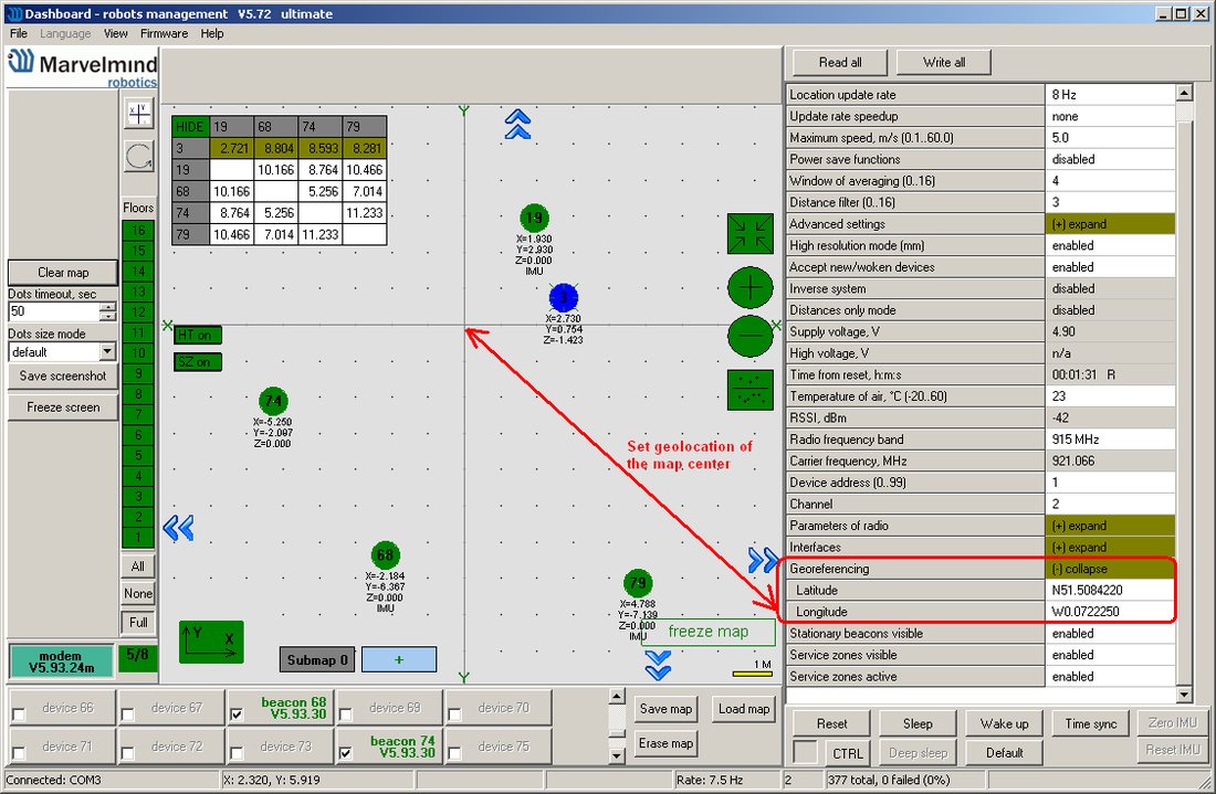
GPS coordinates are calculated according to specified georeference point and WGS-84 Earth model.
More, detailed,
Lat= Lat_ref + y*9.013373
where
Lat – latitude, microdegrees
Lat_ref – georeference latitude, microdegrees
y – y coordinates in Marvelmind system, meters
Long= Long_ref + x*8.98315/cos(Lat_ref/1000000)
Long – longitude, microdegrees
Long_ref – georeference longitude, microdegrees
Lat_ref – georeference latitude, microdegrees
x – x coordinates in Marvelmind system, meters
General agreements for time
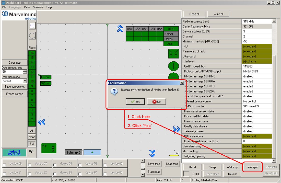
After power on, mobile beacon counts time starting from 2016.08.01 00:00:00. User can synchronize time with computer clock as shown on following screenshot.
Description of “NMEA0183” messages implementation
NMEA 0183 messages are ASCII coded text frames, consist of several parts, separated by commas, and terminated by end of line. Before end of line, every message is finished by ‘*’ symbol, followed by two symbols of checksum, calculated according to NMEA 0183 standard.
Each part of NMEA 0183 message represents certain parameter.
Below is description of all supported messages and parameter fields.
Messages format is taken from NMEA 0183 standard version 3.01, January 1, 2002.
1. $GPRMC -Recommended Minimum Specific GNSS Data
Supported hardware:
Super-Beacon: supported
Industrial Super-Beacon: supported
Modem HW5.1: supported (starting from SW V7.000)
Super-Modem: supported (starting from SW V7.000)
Mini-RX (Badge, Helmet, etc.): supported with the UART cable
Mini-TX: not supported in the current HW version
Mini-TX-2: supported with the UART cable
Modem HW4.9: not supported
Beacon HW4.9: supported
Beacon HW4.5: supported
General format from NMEA 0183 standard:
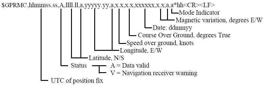
Description of fields implementation:
1.1. ‘$GPRMC’ – designation of message type
1.2. ‘hhmmss.ss’ – UTC position fix
According to general agreements, time is counted from default 2016.01.01 or synchronized with computer clock.
1.3. ‘A’ – status
‘A’ value is sent if last position update was successful
‘V’ value is sent if any error occurred in last position update
1.4. ‘llll.llllll,a’ – latitude, N/S
According to general agreements (see above), latitude corresponds to the Y coordinate relative to georeference location. Latitude is presented with 6 digits of decimal-fraction of minutes, which gives resolution not more than 2 mm,
1.5. ‘yyyyy.yyyyyy,a’ – longitude, E/W
According to general agreements (see above), longitude corresponds to the X coordinate relative to georeference location Longitude is presented with 6 digits of decimal-fraction of minutes, which gives resolution not more than 2 mm.
1.6. ‘x.x’ – speed over ground, knots
Marvelmind system measures the coordinates; the speed is calculated from dynamics of coordinates with applying of some filtering. Optionally, it can use IMU fusion for speed calculation.
1.7. ‘xxxxxx’ – date: ddmmyy
According to general agreements, time is counted from default 2016.01.01 or synchronized with computer clock.
1.8. ‘x.x,a’ – magnetic variation
This parameter value is always a null field.
1.9. ‘a’ – mode indicator
‘A’ value (autonomous mode) is sent if last position update was successful
‘N’ value (data not valid) is sent if any error occurred in last position update
2. $GPGGA -Global Positioning System Fix Data
Supported hardware:
Super-Beacon: supported
Industrial Super-Beacon: supported
Modem HW5.1: supported (starting from SW V7.000)
Super-Modem: supported (starting from SW V7.000)
Mini-RX (Badge, Helmet, etc.): supported with the UART cable for Mini-Rx
Mini-TX: not supported in the current HW version
Mini-TX-2: supported
Modem HW4.9: not supported
Beacon HW4.9: supported
Beacon HW4.5: supported
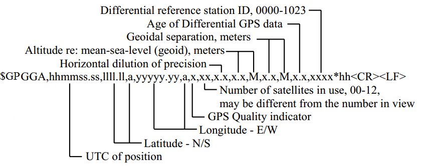
Description of fields implementation:
2.1. ‘$GPGGA’ – designation of message type
2.2. ‘hhmmss.ss’ – UTC position fix
According to general agreements, time is counted from default 2016.01.01 or synchronized with computer clock.
2.3. ‘llll.llllll,a’ – latitude, N/S
According to general agreements (see above), latitude corresponds to the Y coordinate relative to georeference location. Latitude is presented with 6 digits of decimal-fraction of minutes, which gives resolution not more than 2 mm
2.4. ‘yyyyy.yyyyyy,a’ – longitude, E/W
According to general agreements (see above), longitude corresponds to the X coordinate relative to georeference location. Longitude is presented with 6 digits of decimal-fraction of minutes, which gives resolution not more than 2 mm
2.5. ‘x’ – GPS quality indicator
‘1’ (GPS SPS Mode, fix valid) value is sent if last position update was successful
‘0’ (Fix not available or invalid) value is sent if any error occurred in last position update
2.6. ‘xx’ – number of satellites in use
Always ’08’ in current implementation.
2.7. ‘x.x’ – horizontal dilution of precision
Always ‘1.2’ in current implementation.
2.8. ‘x.x, M’ – altitude re: mean-sea-level (geoid), meters
This corresponds to the Z coordinate according to general agreements.
2.9. ‘x.x, M’ – geoidal separation, meters
Always ‘0.0, M’ value is transmitted.
2.10. ‘x.x’ – age of differential GPS data
This parameter value is always a null field, DGPS is not used.
2.11. ‘xxxx’ – differential reference station ID
This parameter value is always a null field.
3. $GPVTG -Course Over Ground and Ground Speed
Supported hardware:
Super-Beacon: supported
Industrial Super-Beacon: supported
Modem HW5.1: supported (starting from SW V7.000)
Super-Modem: supported (starting from SW V7.000)
Mini-RX (Badge, Helmet, etc.): supported with the UART cable for Mini-Rx
Mini-TX: not supported in the current HW version
Mini-TX-2: supported
Modem HW4.9: not supported
Beacon HW4.9: supported
Beacon HW4.5: supported
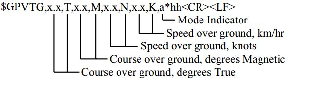
Description of fields implementation:
3.1. ‘$GPVTG’ – designation of message type
3.2 . ‘x.x, T’ – course over ground, degrees True
According to NMEA standard, the course is the angle between vector of speed and direction to the north. As shown in general agreements above, the Y axis is taken as direction to north.
3.3. ‘x.x, M’ – course over ground, degrees Magnetic
In current implementation, magnetic course is same as true course.
3.4. ‘x.x, N’ – speed over ground, knots
Marvelmind system measures the coordinates; the speed is calculated from dynamics of coordinates with applying of some filtering. Optionally, it can use IMU fusion for speed calculation.
3.5. ‘x.x, K’ – speed over ground, km/hr
It is the same speed in another units
3.6. ‘a’ – mode indicator
‘A’ value (autonomous mode) is sent if last position update was successful
‘N’ value (data not valid) is sent if any error occurred in last position update
4. $GPZDA -Time & Date
Supported hardware:
Super-Beacon: supported
Industrial Super-Beacon: supported
Modem HW5.1: supported (starting from SW V7.000)
Super-Modem: supported (starting from SW V7.000)
Mini-RX (Badge, Helmet, etc.): supported with the UART cable
Mini-TX: not supported in the current HW version
Mini-TX-2: supported with the UART cable
Modem HW4.9: not supported
Beacon HW4.9: supported
Beacon HW4.5: supported
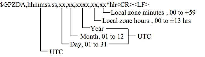
According to general agreements, time is counted from default 2016.01.01 or synchronized with computer clock.
Description of fields implementation:
4.1. ‘$GPZDA’ – designation of message type
4.1. ‘hhmmss.ss’ – UTC
Time (hours, minutes, seconds).
4.2. ‘xx’ – day, 01 to 31
Day.
4.3. ‘xx’ – month, 01 to 12
Month.
4.4. ‘xxxx’ – year
Year.
4.4. ‘xx – local zone hours
Local zone is always “00” hours.
4.5. ‘xx – local zone minutes
Local zone is always “00” minutes.
5. $GPHDT – Heading
Supported hardware:
Super-Beacon: supported
Industrial Super-Beacon: supported
Modem HW5.1: supported (starting from SW V7.000)
Super-Modem: supported (starting from SW V7.000)
Mini-RX (Badge, Helmet, etc.): supported with the UART cable
Mini-TX: not supported
Mini-TX-2: supported with the UART cable
Modem HW4.9: not supported
Beacon HW4.9: not supported
Beacon HW4.5: not supported
Note you need MMSW0002 license to enable streaming of this packet.
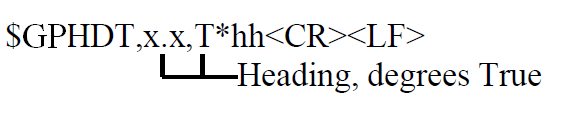
5.1. ‘$GPHDT’ – designation of message type
5.2. ‘x.x, T’ – heading, degrees True
This is a heading angle calculated by using paired beacons or paired microphones feature with fusion with the gyroscope.
Examples of NMEA data receiving
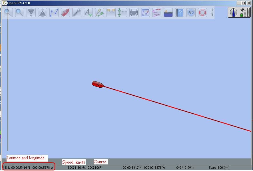
On the next screenshot is example of data, received from mobile beacon, connected via USB (virtual COM port) to the OpenCPN software, running on the computer under MS Windows.