Low-latency real-time IMU sensor fusion for precise indoor positioning systems
Executive summary
With the real-time low-latency IMU sensor fusion, you can get:
- Up to 500 Hz location update rate
- 5-25 ms latency – depending on the type of mobile object movement and settings
- 3D tracking. 1D and 2D tracking is supported as well (of course 🙂
- Currently, supported IA only. Support for NIA and MF NIA coming as well
- The Paired Beacons configuration is required for Location + Direction and a two-wire connection between mobile beacons
- The functionality is enabled by the MMSW0021: Realtime Ultrasound + IMU sensor fusion license


Practical hints and advice
Assess what kind of IMU sensor fusion you need
First of all, choose between several flavors of IMU sensor fusion. Remember, you don’t need the IMU sensor fusion per se. You need what it gives: higher location update rate, lower latency, more robustness to short-time occlusions, higher accuracy. IMU sensor fusion is one of the ways to achieve it but not the only one:
- MMSW0009: Ultrasound + IMU sensor fusion (post-processing) and Fast Indoor Positioning System: IMU and Ultrasonic Sensor Fusion – If post-processing is good enough for you, use it. It will always be better than the MMSW0021: Realtime Ultrasound + IMU sensor fusion in terms of accuracy and robustness, because for post-processing, IMU sensor fusion has more data and can make better decisions about the fusion. It works with or without the Paired Beacons configuration
- MMSW0017: High update rate extrapolation – use this if you have mobile objects with relatively predictable movements: go-karts, speed skaters, and similar. Of course, during the crush, it won’t be predictable anymore, and the algorithm will struggle. But most of the time, you will have very good tracking with virtually zero or even negative latency (extrapolation/forecasting). It works with or without the Paired Beacons configuration
- MMSW0021: Realtime Ultrasound + IMU sensor fusion – the key benefit of this flavor is the low latency of location data. It is the most IMU sensor fusion branch of all IMU sensor fusion algorithms in the common meaning of the phrase. It currently requires the Paired Beacons configuration for the mobile beacons (hedges) and works in IA only
- IMU sensor fusion for direction. It is a real IMU sensor fusion, but for angular data only – not for location. The Paired Beacons configuration is required. You have a very high angular resolution, defined by the gyroscope, with no gyroscope drift because it is sensor-fused and constantly corrected by the Paired Beacons configuration. The Paired Beacons configuration for the mobile beacons is a must. To get it with Marvelmind protocol, you don’t need any optional licenses. For NMEA: MMSW0002: Heading packet GPHDT for NMEA0183. For uBlox: MMSW0003: UBX (u-blox) protocol for PX4
- Maybe, you don’t need the IMU sensor fusion at all, and proper settings will give you a high-enough update rate and a low-enough latency:
Only the newer beacons with -4 or later in the name supported
Currently supported mobile beacons are:
- Super-Beacons-4
- Industrial Super-Beacons-4
- Industrial-RX-4 with Omni
- Industrial-RX-4 with Horn
Newer hardware version of these and other mobile beacons likely to support the MMSW0021: Realtime Ultrasound + IMU sensor fusion.
To avoid doubts:
- Super-Beacons, Super-Beacons-2, Super-Beacons-3, Industrial Super-Beacons-2 and -3 and Industrial-RX-2 and -3 and other more mature devices are not supporting the MMSW0021: Realtime Ultrasound + IMU sensor fusion as mobile devices
- However, for stationary beacons, there are no restrictions and they can be used as stationary beacons easily, if they can work as as stationary beacons in IA. For example, Industrial-RX cannot act as a stationary beacon in IA, because it doesn’t have transducers at all and cannot emit ultrasound. It is not related to this feature, but the basics about the architecture requirements must not be forgotten. Even very mature Beacons HW v4.9 can be used as stationary beacons
The Paired Beacons configuration required
Currently the feature MMSW0021: Realtime Ultrasound + IMU sensor fusion works only for the Paired Beacons configuration for the mobile beacons. Why? – because there is no practical way determine the direction of the single mobile beacon (yaw axis) in static with high-enough accuracy.
Yes, it is possible to determine the direction in the yaw, when the mobile object is already moving, lock to it, and track and correct the drift. We successfully do it in the Marvelmind DJI drone solution:
However, this puts additional requirements on the initial placement of the mobile object against the system coordinates or on the initial 0.5-1 m of the movement – until the yaw axis direction lock occurs. In some cases, it is a too much of a restriction. In some cases, it is a neat solution and you don’t need to carry two mobile beacons. Such sub-flavor of the MMSW0021: Realtime Ultrasound + IMU sensor fusion feature is coming. It is likely be more fragile than the base sub-flavor with the Paired Beacons configuration, because it will have less data, generally speaking. But in some cases, it is a strong enabler, because the user simply may not have enough space for the Paired Beacons configuration, which requires, at least, 20-30-cm base between the mobile beacons.
The Paired Beacons - basic two wires between the mobile beacons required
For the Paired Beacons configuration, the mobile beacons must be connected by two wires:
- UART TX from the slave beacon (on the right) must be connected to the UART RX pin on the external 4×4 pins (or equivalent in other beacons) of the master Super-Beacons
- Grounds of both beacons to be connected as well
See more about the Paired Beacons configuration in the Operating Manual.
Mobile beacons' relative placement does matter
- The base between the microphones (or centers) of the beacons, at least 20-30 cm, is recommended. Shorter distances may work as well, but the robustness will gradually fade
- The master beacon must be on the left of the pair
- The USB connector of the Super-Beacon or the 7-pin connector of the Industrial beacon must be on the back of the pair. It is possible to rotate. But then the settings must be changed
- Axis shown for the Super-Beacons. They are not shown for the Industrial Super-Beacon (the picture may be updated later). However, it is likely different because the placement of the IMU chip is different on the boards
Connectivity to user devices and methods to avoid extra latency
Since the biggest kicker for the feature MMSW0021: Realtime Ultrasound + IMU sensor fusion is its low-latency of the location data, it is crucial to clearly understand how to get the location data and not to introduce extra latency due to the interfaces or operating systems:
- Regular UART from the master mobile beacon (hedge or hedgehog) using the 4×4 pins of the Super-Beacon or pins inside the 7-pin data connector of Industrial beacons is the best and easiest way to get the low-latency location data without noticeable extra-latency
- Via USB from the master hedge (additional latency ~ 1 ms + latency of the USB driver (OS dependent)). The biggest concern is the unpredictability of the OS latency and its jitter. The extra latency is difficult to assess – from unnoticeable to substantial. The potential latency jitter due to the OS uncontrollable delays is another concern. In the reality, however, these concerns may be over-exaggerated and then such connectivity is even simpler than the wires from the UART (see above) because it uses USB
- Via USB/UART of additional Modem HW v 5.1 with special firmware in the Split Modem Architecture (additional latency: ~ 1ms via radio at 500 kbps + UART/USB latency (see above)). This is the best way to get the low-latency data on the modem’s side – not on the mobile beacons’ side – when you want to track something with the high location update rate and the low latency
- Via UDP from Dashboard with master hedge connected via USB (additional latency ~ 1 ms + latency of USB driver + latency of UDP transfer (typ. 3…50 ms depending on your network))
- Via REST or MQTT from Dashboard with master hedge connected via USB (additional latency ~ 1 ms + latency of USB driver + latency of REST/MQTT transfer). Also, difficult to assess the total extra latency. But it is supported as well
- Via UDP/REST/MQTT/log from Dashboard with modem HW v 5.1 with special firmware in the Split Modem Architecture (additional latency same as for hedge connection to Dashboard + ~ 1ms via radio at 500 kbps)
- Via log file in Dashboard with master hedge connected via USB (for post processing – latency n/a)
Not a major practical restriction, but the current limit for the acceleration of the mobile beacons is 16 g, which is far higher than regular mobile objects experience in real life, unless they hit something hard. However, when they hit something so hard, the IMU sensor fusion or sudden lack of perfect tracking due to over-acceleration is probably not the highest concern anyway. Nevertheless, keep that upper limit in mind. If your requirements include higher acceleration or you have other concerns, please never hesitate to send us your request to info@marvelmind.com.
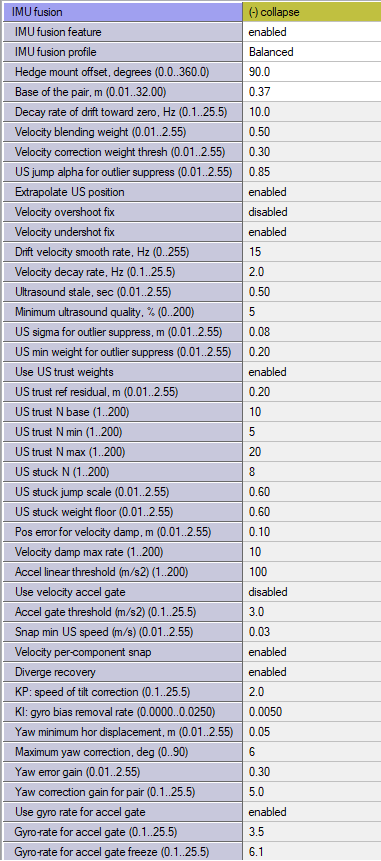
Dashboard settings
There are many settings linked with the MMSW0021: Realtime Ultrasound + IMU sensor fusion feature. Remember, the feature is for the advanced users only. If you a novice, please do step-by-step from the simplest configurations; confirm perfect tracking first; and only after you familiarize yourself with the system, start using this feature: Step-by-step approach and its importance to success.
What is IMU sensor fusion after all? ...
There are several key points to remember when we are talking about IMU sensor fusion for precise indoor positioning systems:
- Sensor fusion by definition means more than one source of data in the attempt to combine the best from fused worlds, for example: IMU + Ultrasound indoor positioning, or IMU + Ultrasound IPS + odometry, or IMU + Ultrasound IPS + visual … – there are many potential sources to fuse
- We don’t see the sensor fusion approach as a “single algorithm that rules them all” – it is a tree of solutions with multiple branches of sensor fusion, and IMU + ultrasound is just one of many options. As well as the current implementation is one of the branches. More to branches/flavors of the IMU sensor fusion to come. The users must clearly distinguish between them to choose the best for the particular scenario, because there are always trade-offs
When we refer to IMU (3D accelerometer + 3D gyroscope) sensor fusion, we typically mean of the IMU data with an ultrasound indoor positioning system data, where the best of the both world is taken and fused together.
Often, it also includes other data sources: the Paired Beacons for Location + Direction, odometry, and embedding the mobile object’s model in some way.
Note, that we don’t typically fuse with magnetometers because we focus on indoor solutions and magnetometers may not work well indoors due to strong distortion of the Earth magnetic field by the ferromagnetic materials around and high currents that produce their own magnetic fields that interfere with the Earth magnetic field. Such a problem doesn’t exist always. However, we cannot rely on magnetometers in general. Thus, we are using the Paired Beacons configuration for Location + Directions: Boxie 2 – driving intro short.
Having said that, we don’t exclude magnetometers entirely. In some cases, the environment is GNSS-denied but the Earth magnetic field is available and magnetometers can be used. In this case, it is either an external board connected to the Super-Beacon-4 or Industrial Super-Beacon-4 via the 4×4 expansion connector, typically, via I2C or SPI or some other arrangement. Request that, if the Paired Beacons configuration is not suitable for your case.
It is hard to track just anything with an IMU sensor, without a clue what we are tracking. Some knowledge about the object is nearly essential: “forklifts don’t fly”, “forklift’s fork can move in 3D”, “quick 3D maneuvers can be expected from a racing drone or a half-pipe ski jumper, but improbable by a 2D driving delivery robot”, etc. Thus, there are many settings. Maybe, too many. We made several profiles so that you wouldn’t need to dig too deep, but, if you want, you have a nearly infinite control of the IMU sensor fusion system.
Choose your goals wisely and realistically
Also, it is very important to clearly understand what exactly you want to achieve with the sensor fusion. IMU sensor fusion is a very powerful solution. Still, there are trade-offs and not everything can be achieved at the same time. You have to choose between usual suspects: accuracy, update rate, latency, stability, robustness, flexibility, complexity, price, and similar.
So, what exactly do you want to achieve with the sensor fusion?
- High update rate?
- Low latency?
- Higher accuracy of positioning data?
- More resistance or occlusions or source of noise that can lead to jumps?
That is one of the major reasons why the sensor fusion is not a one-serves-all solution but a tree of solutions and there are different profiles withing the branches of the tree with specific focus on the particular needs.
Low latency and high update rate

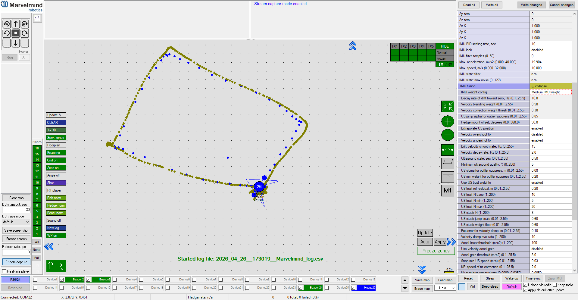
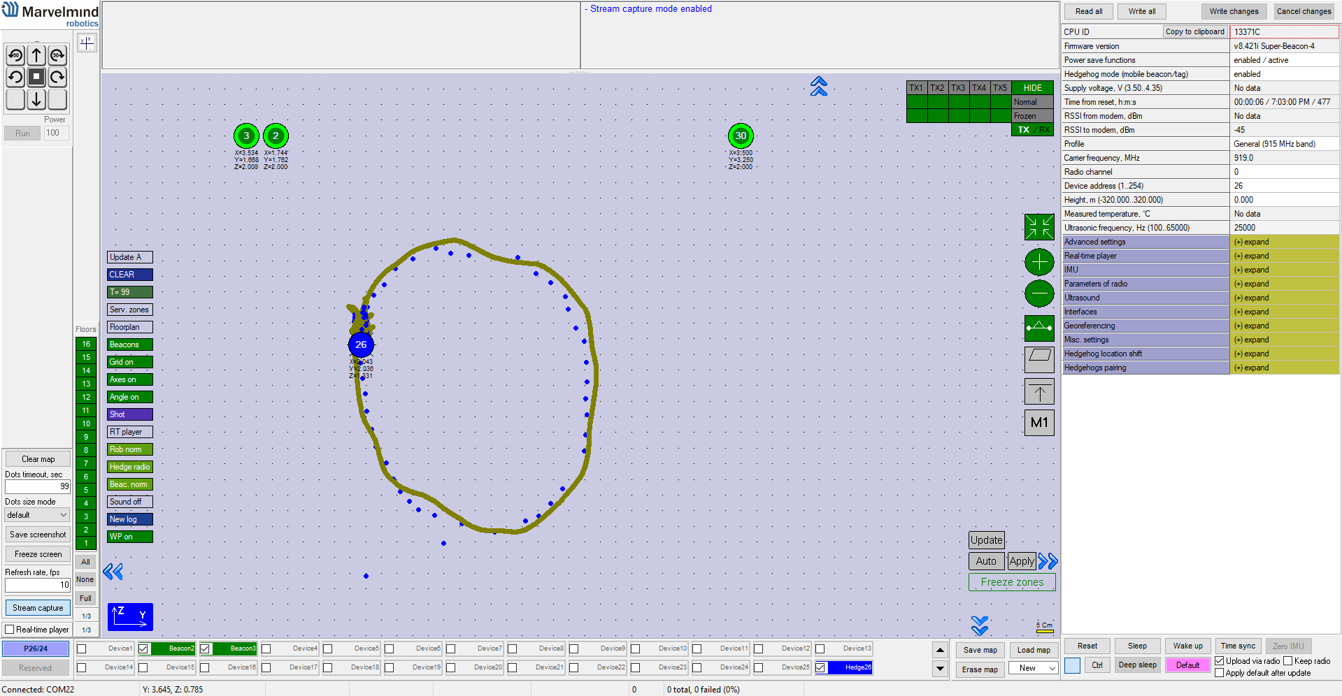
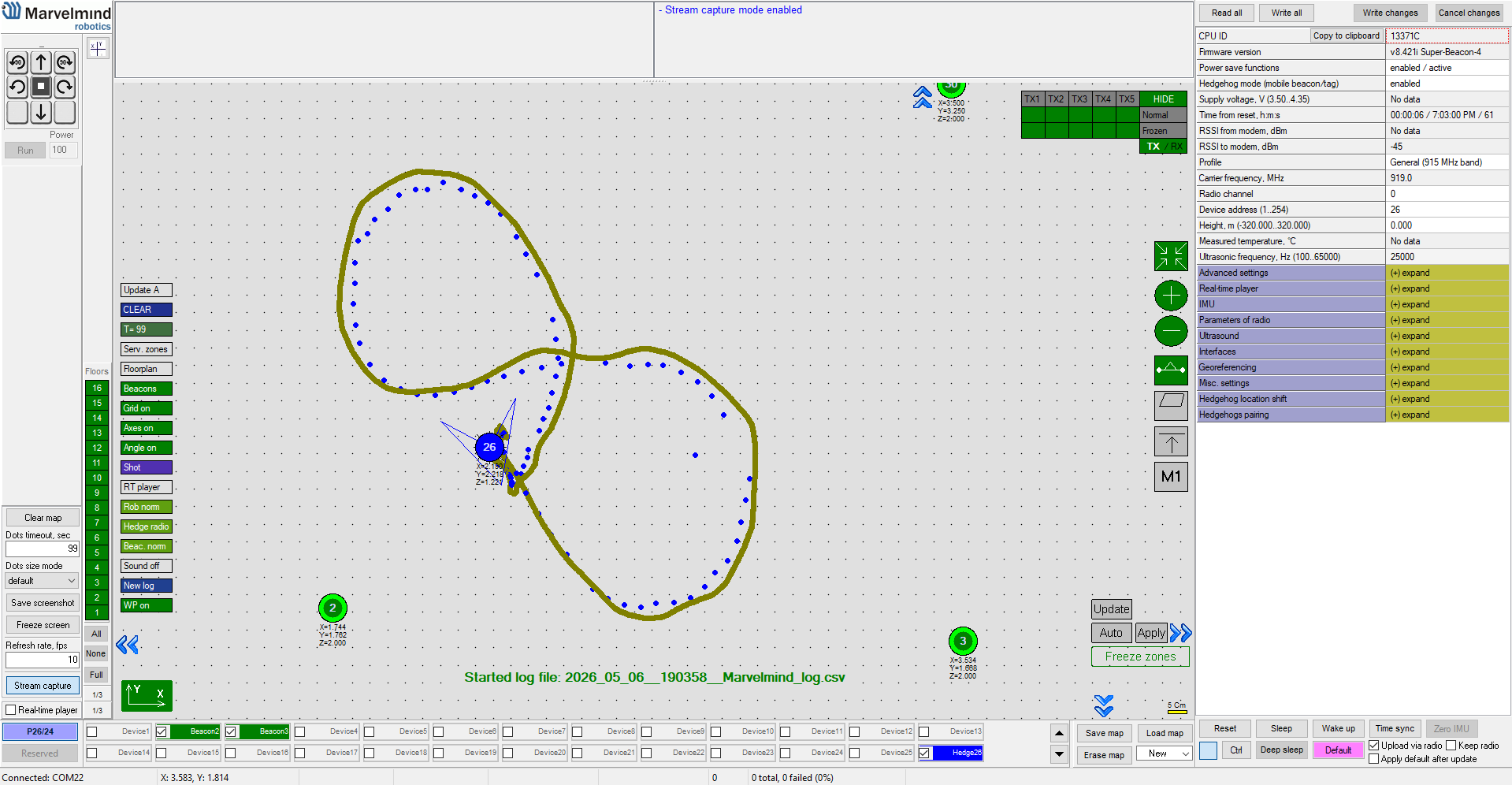
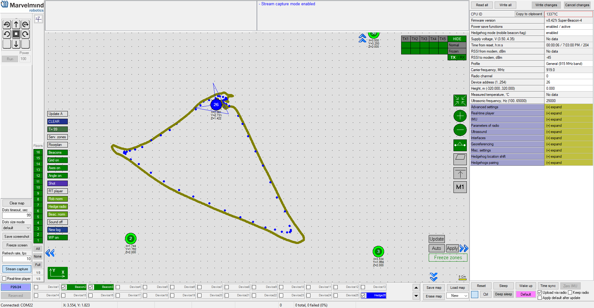
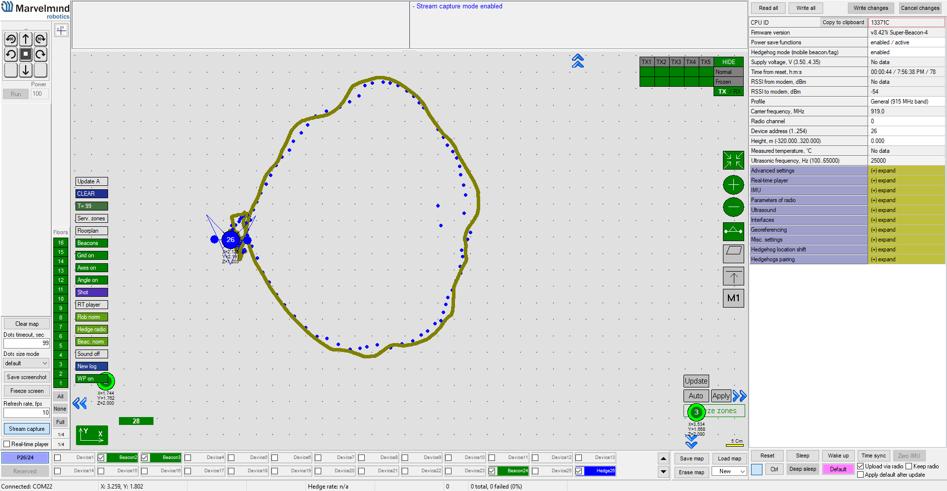
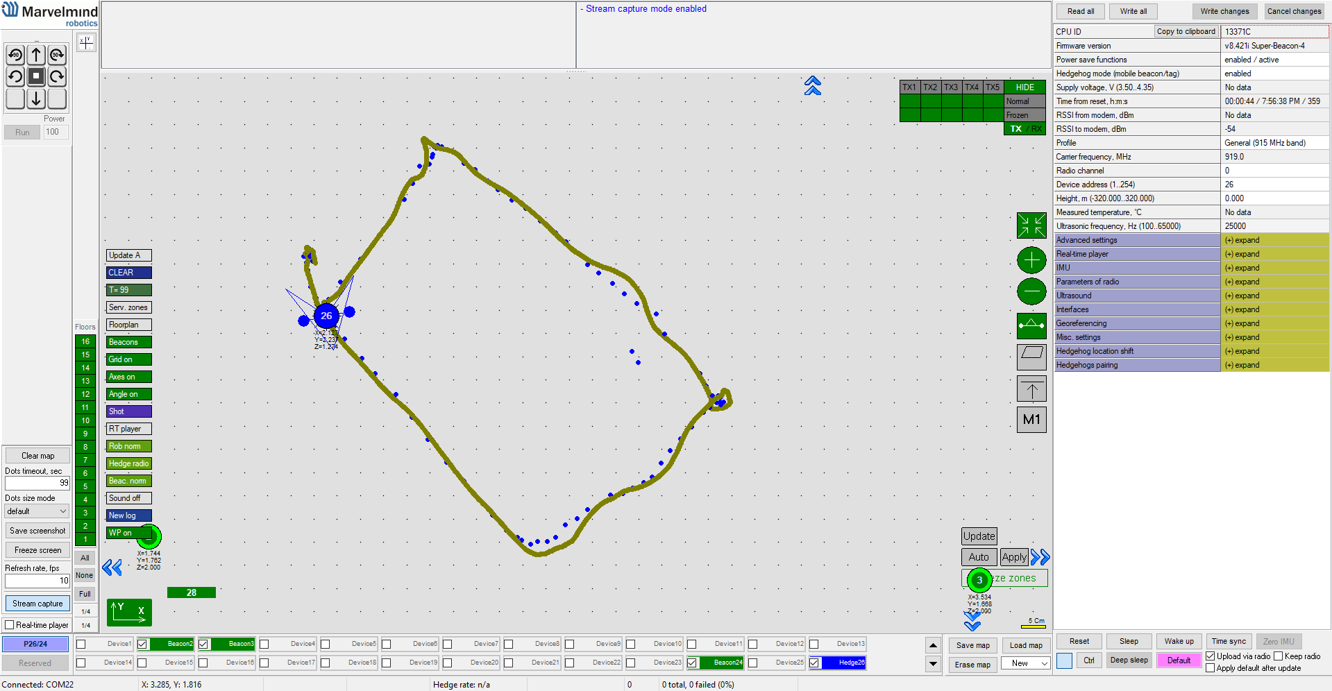
Higher robustness to short occlusions or noise
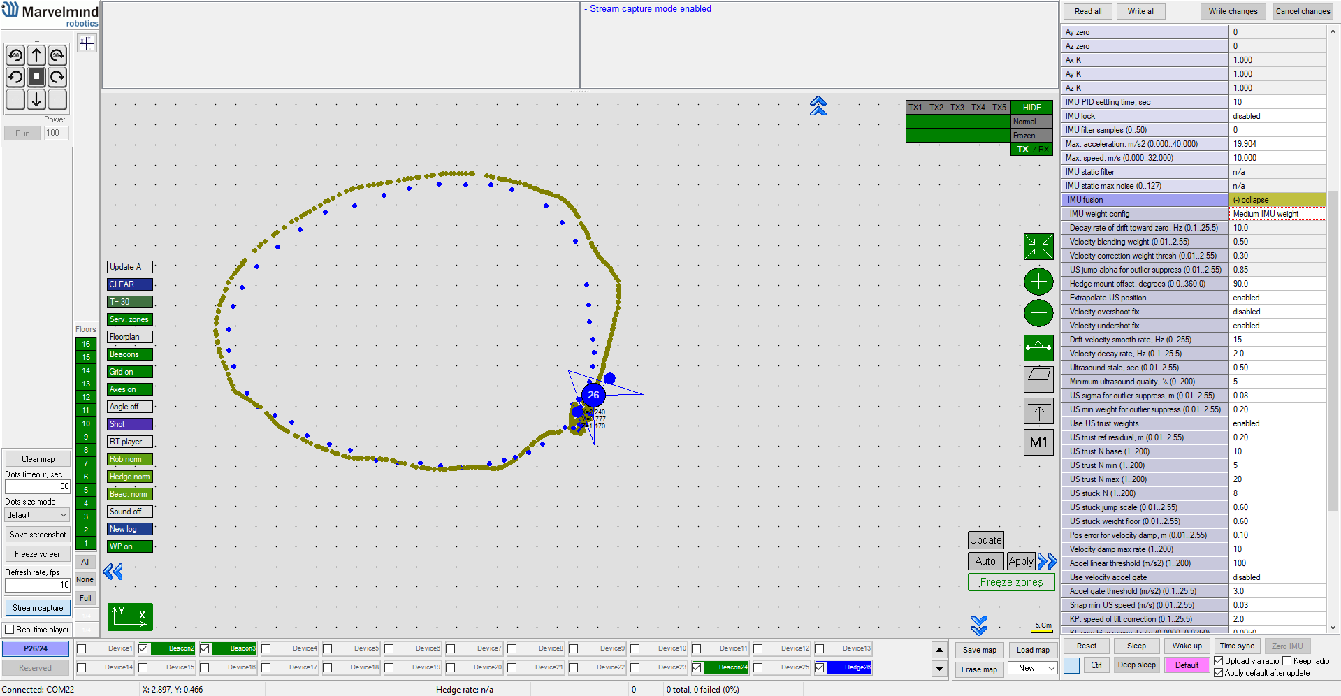
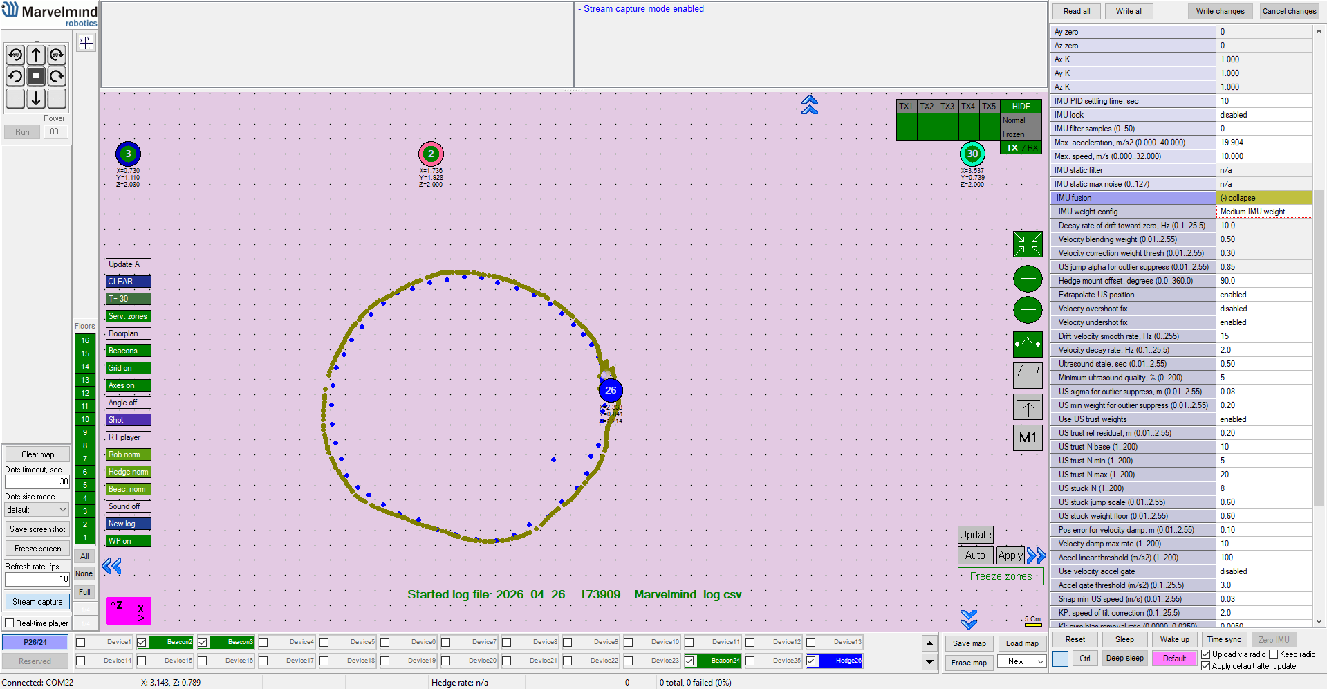
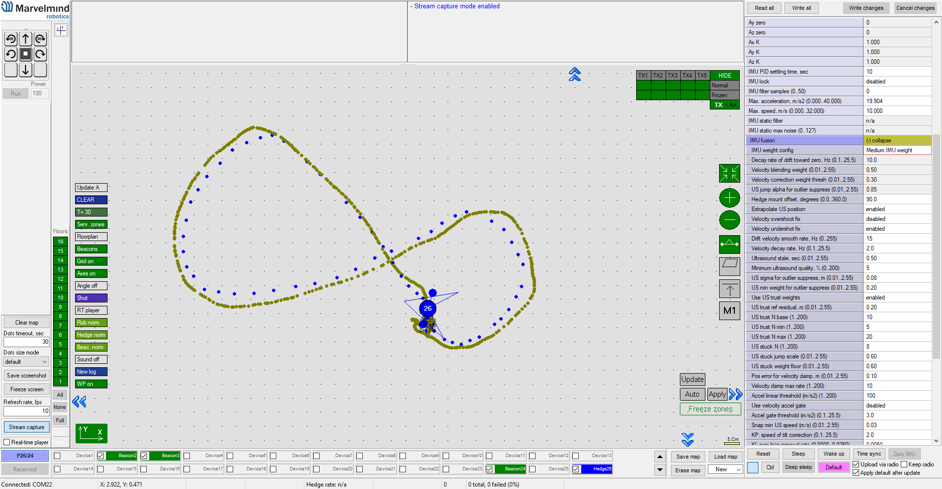
The nature of the sensor fusion results in the higher robustness to location jumps due to the short occlusions or noise. Check the pure ultrasound-based tracking and tracking after the sensor fusion.


IMU sensor fusion is too perfect. Where is the catch?...
The low-latency IMU sensor fusion is indeed a very powerful feature that produces very impressive results. However, the users must clearly understand the requirements as well:
- It is a complex feature with a lot of settings. Thus, it is for the experienced users. If you are stuck or unsure, please always ask via info@marvelmind.com. We combined them into profiles so that you don’t have to set anything – you don’t even have to enable the feature. It will be automatically enabled as soon as you purchased the license. But there are very many settings, in the Advanced profile, so you can tune to your specific mobile beacon model as close as you wish, thus, achieving as good results as possible
- It requires the Paired Beacons configuration. Other flavors (with a single beacon but some extra requirements for initial placement) or a version with an external magnetometer are possible and coming. The current and the recommended one is the most robust version of them all
- The IMU sensor fusion assumes and guesses (forecasts) a lot because it operates with incomplete and unverified data by the definition of the real-time approach. Thus, in cases when you have poor ultrasound tracking, the IMU sensor fusion may not fix it but amplifies it. With the shorter jumps or shorted occlusions, it improves the overall tracking by effectively absorbing or neglecting thus ultrasound tracking jumps
Overall, it is a very potent feature, despite all our words of caution, that highly improves tracking specs from several dimensions at the same time: latency, update rate, robustness, and even accuracy.
Settings

Multiple (contradicting) goals = several IMU sensor fusion branches
High location update rate is easy. Low latency is naturally hard:
- You can achieve a high location update with multiple starting from basic interpolation – without a sacrifice of the accuracy, because the objects are sufficiently inertial anyway. This is our basic Realtime Player, which is already embedded inside the Dashboard. If the objects are too agile for the given real ultrasound location update rate, then interpolation wouldn’t work, of course, and you need something more sophisticated, like the realtime IMU sensor fusion, which is the main topic of this page
- You can do IMU sensor fusion post-processing, which we have had available for a few years now. It is a true sensor fusion. It will return a true high update rate without “cutting the corners”. But it will come with a relatively high latency. Often, it is the best and recommended solution for anything that is being tracked and that is not required an immediate reaction to the location, for example: sport. You can track impressive sport somersaults. The somersault takes a fraction of a second. But the tracking result is available in 1-2 seconds after. Or you teach your very high-speed racing car to drive the corners optimally. You first record the manual driving – precise tracking with the post-processing IMU sensor fusion, then you do some AI teaching into the loop. It is not critical whether your get the location data after 10 ms or 10 seconds. As soon as it is not 10 hours, you are typically OK
- In some cases, for example, go-karts, the objects are pretty know – its inertia, driving style, maximum speed, etc. – and you can indirectly embed this information into the model. With the high-enough initial purely ultrasound-based indoor positioning data, you can extrapolate or forecast the location data with zero or even negative latency – it is a forecast, after all. It doesn’t work for all types of mobile objects, for example, people in the warehouse – they are too agile and too unpredictable – but it works very well with a large class of inertial-enough mobile objects. Use it, when it your case. It is an easy and robust system. You don’t have to over-complicate: MMSW0017: High update rate extrapolation
- IMU sensor fusion for Location + Direction is based on the Paired Beacons on the more simple side of the IMU sensor fusion spectrum, because it eliminates the yaw drift but doesn’t deal with the location. It is a true IMU sensor fusion with extremely high angular resolution and no angular drifts or jumps. The angle is taken from the gyroscope with all the benefits of it – high resolution, low noise, very high update rate – and the gyroscope’s yaw drift is eliminated by the Paired Beacons configuration. The pitch and roll drift is eliminated based on the 3D accelerometer data
- And pinnacle of them all is the Realtime Ultrasound + IMU sensor fusion – it is the most advanced and the most complex version of the fusion and all complexity comes from the low-latency part of the requirements
Challenges to overcome with sensor fusion
Sensor fusion aims at overcoming shortcomings of standalone sources of data, for example:
- Ultrasound-based indoor positioning system – the location doesn’t drift; it returns very high accuracy location data; but it can be prone to high-lever acoustic noise or jumps due to occlusions
- IMU (3D accelerometer + 3D gyroscope) returns unbelievable angular resolution, i.e., you can measure the change of the direction with extremely high resolution; it doesn’t jump, because accelerometers and gyroscopes have very low noise and it can return micrometer – not millimeter – but micrometer-level positioning accuracy. However, the IMU drifts and does it very quickly – fractions of the second or small seconds for regular MEMS that used in modern electronics: you know the short-term change of the angle very well, but you don’t know the angle (am I referring to Z – all other angles are trivial with the help of the accelerometer); you could use double-integration of the accelerometer but the accelerometers far from zero biasing, etc., and with the fraction of a second or small seconds you accumulated location error is higher than that of the ultrasound indoor positioning system. So, the IMU lies. Thus, there must be no rosy expectations of purely inertial indoor positioning systems. Unless the fundamentals physics changes radically, there are either impossible or highly imprecise, if compared to the ultrasound-based indoor positioning system
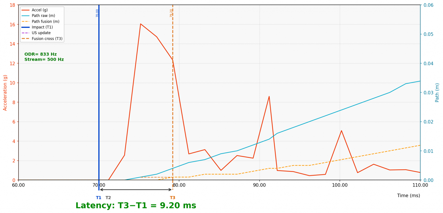
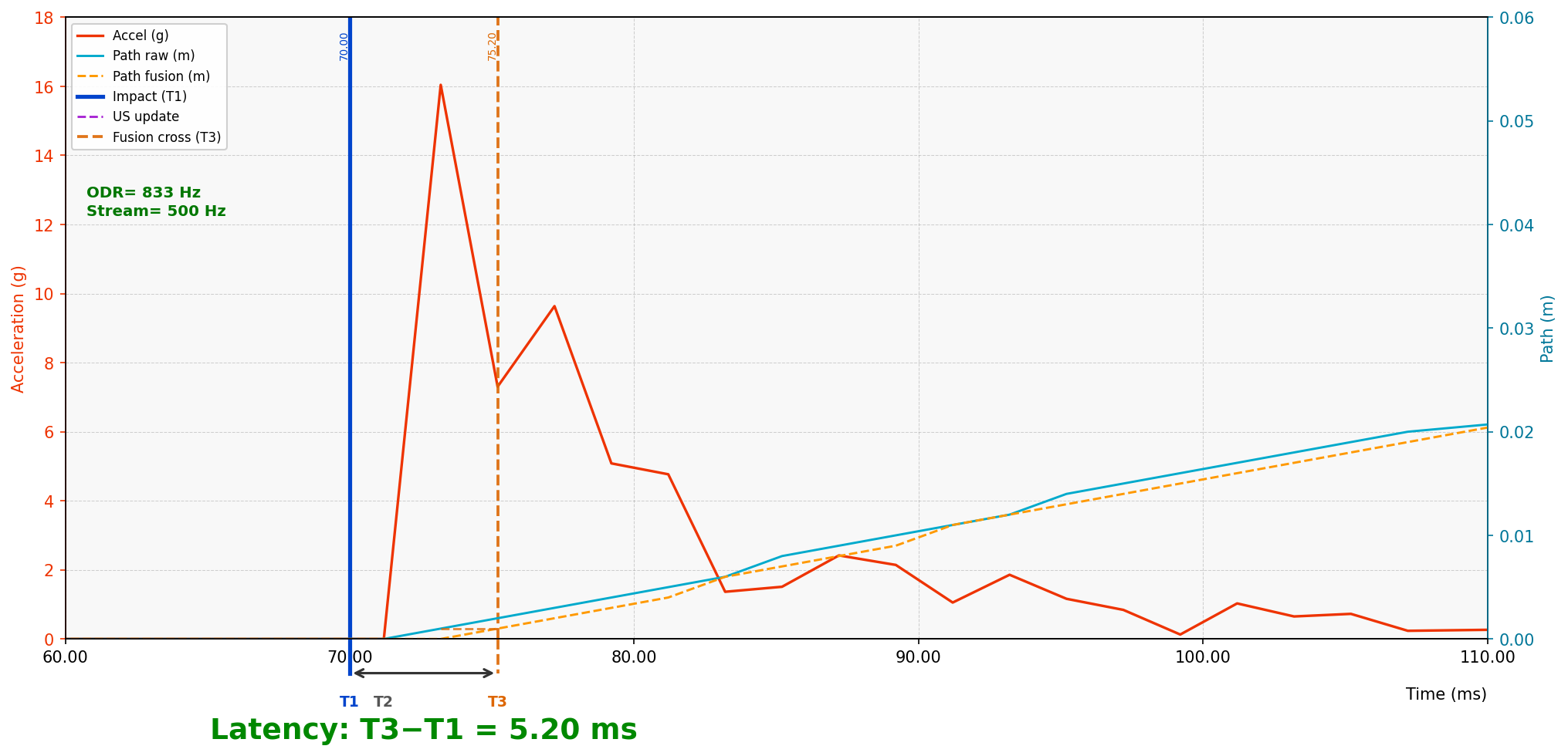
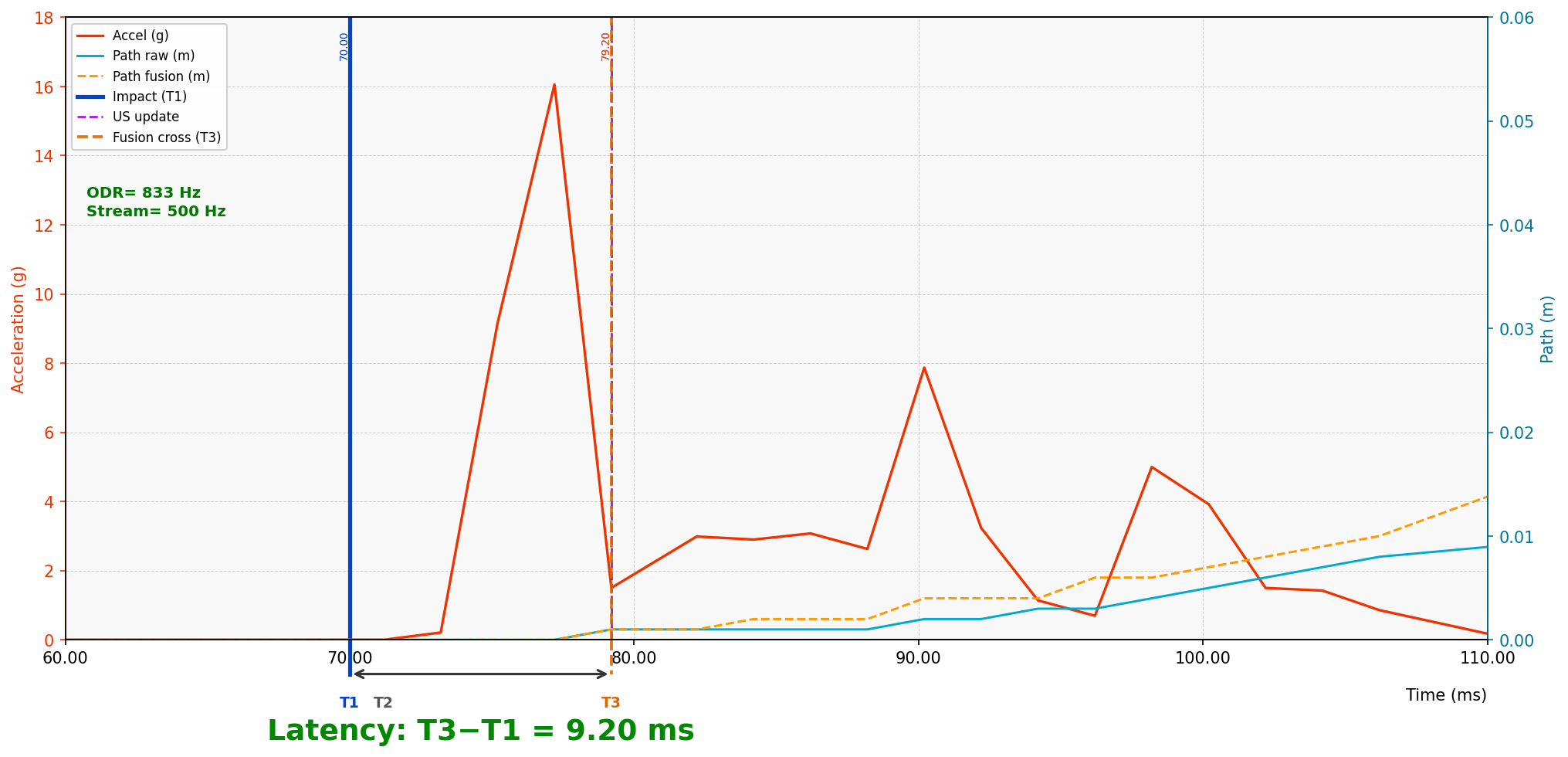
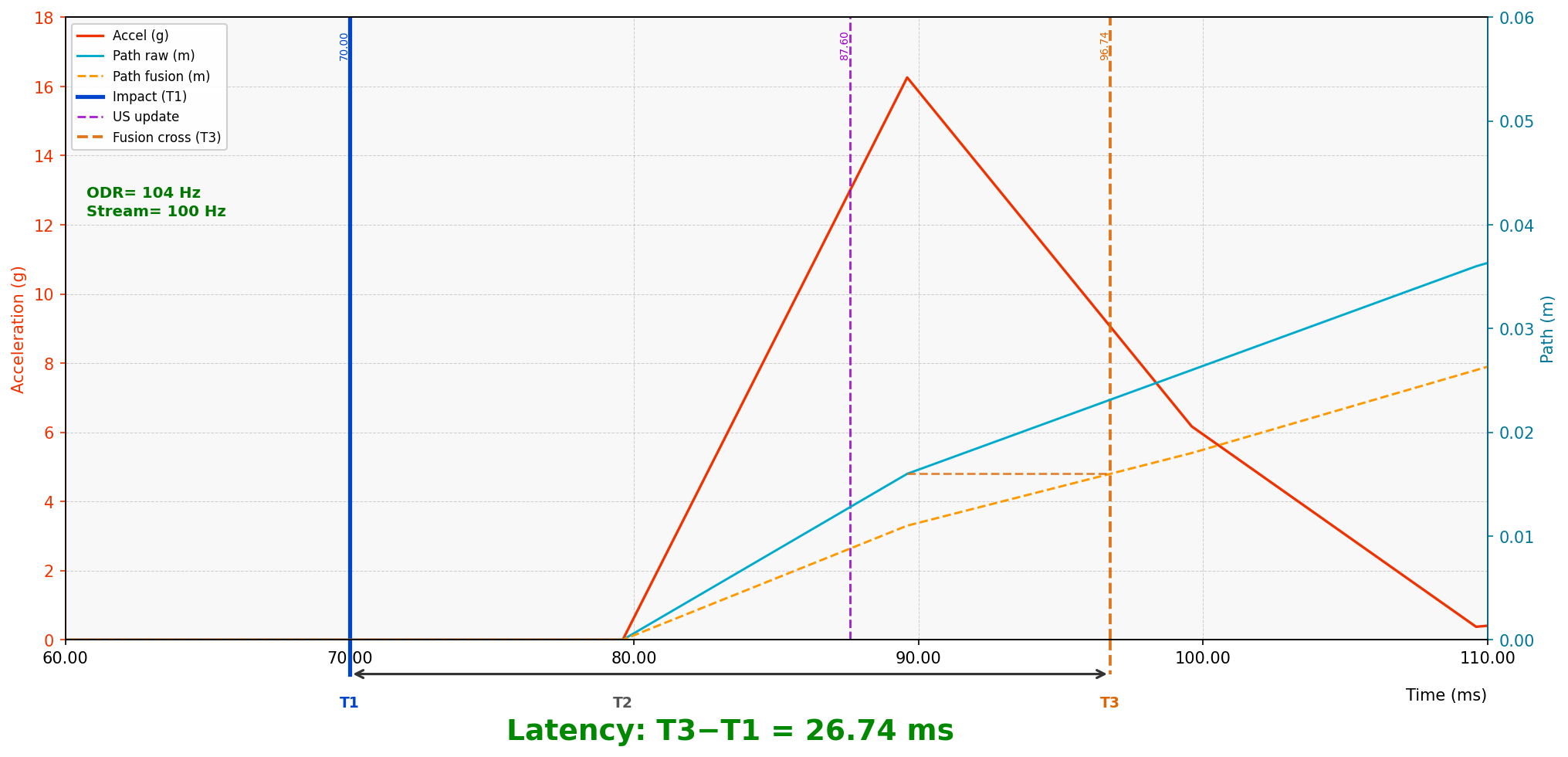
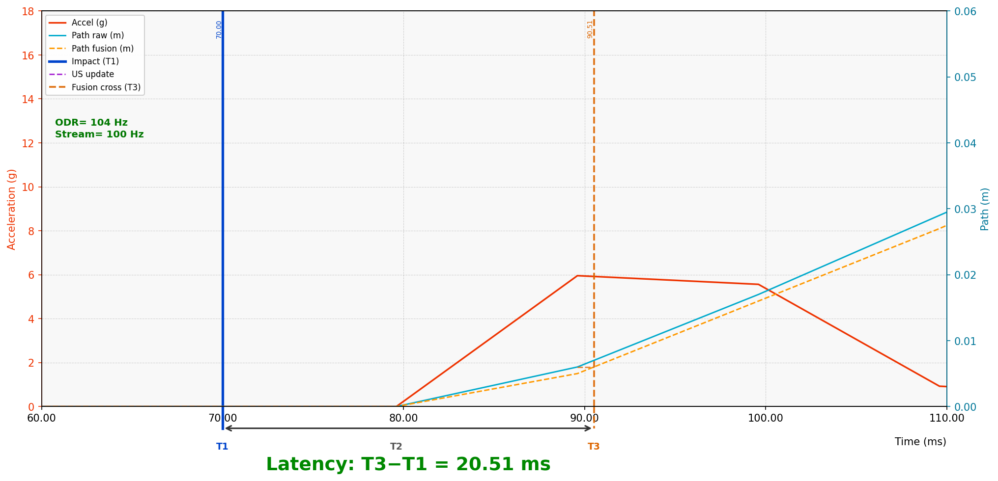
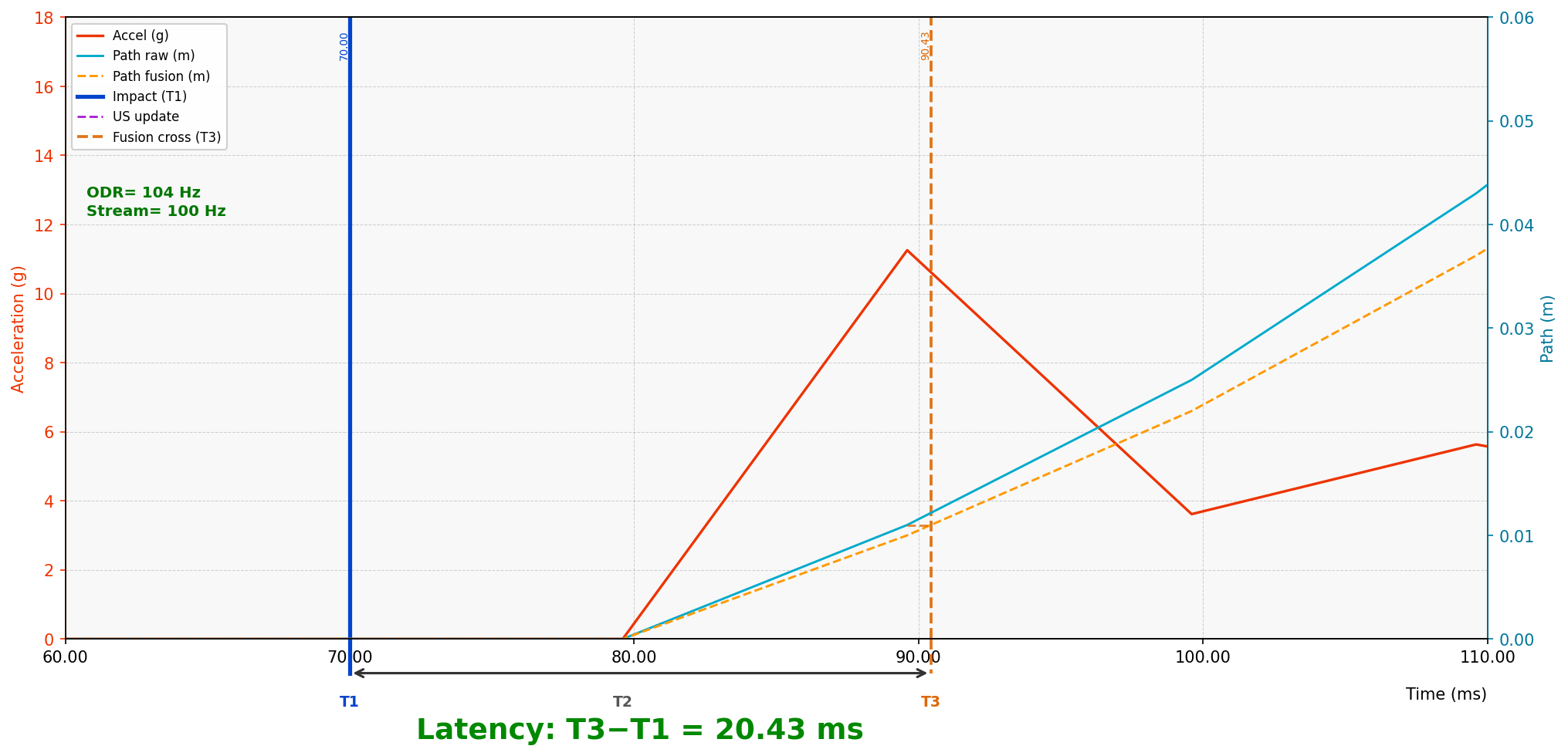
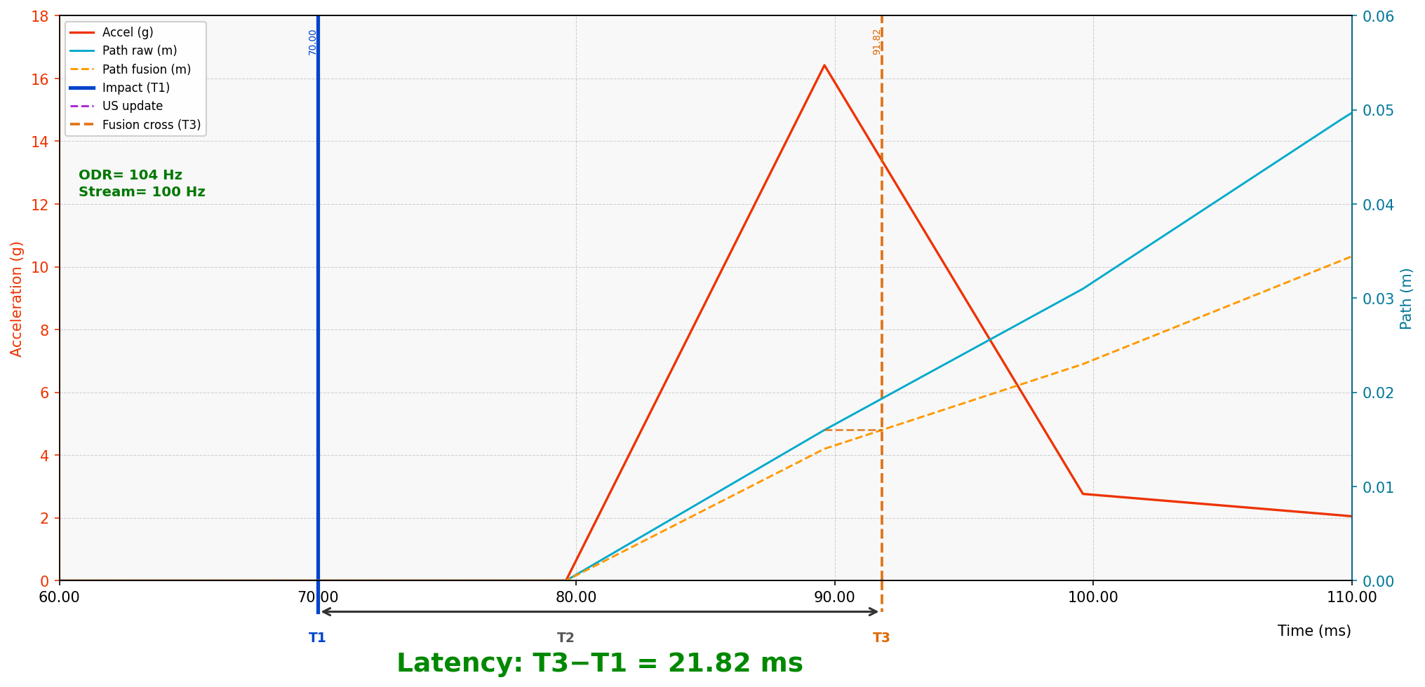
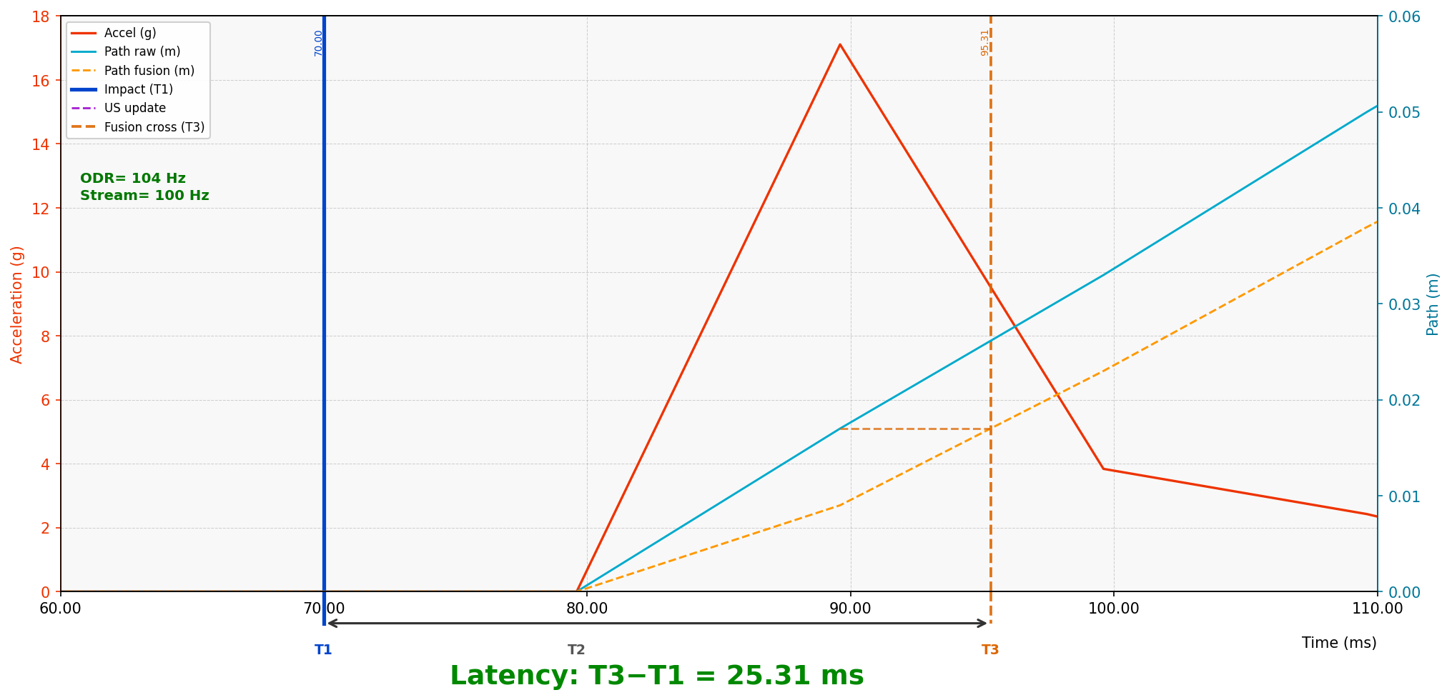
Why low latency is hard to achieve (and even measure)
If you can take the IMU sensor fusion post-processing – take it. It will always be more accurate and more reliable than the real-time IMU sensor fusion:
- More data can be taken into account with post-processing because more data is available – you accumulate it for long and then use it – higher confidence and robustness to jumps due occlusions or noise or other interference
- More data to be taken into account – higher accuracy and higher confidence and higher robustness
With the real-time IMU sensor fusion, you simply don’t have the privilege of more data. To accumulate more data, you need more time. More time = higher latency. Higher latency – IMU sensor fusion post-processing. Works brilliantly, but later.
With the real-time low-latency IMU sensor fusion, you have:
- Historical ultrasound-based location data. Typical update rate 4-20 Hz, i.e., an average latency from the latest ultrasound location update = 1/(location update) = 1/20.. 1/4 sec = 50 … 250 ms, which is OK for the majority of real life industrial applications. However, the if you use only the historic data, you don’t need the IMU – you can rely much easier and often more reliable extrapolation approach, which beautifully works for some types of the mobile objects, but only some
- You have the latest ultrasound location update. Which is great, but you can never trust any data with 100% of confidence. But you don’t have enough information – yet! – to verify whether that the sudden change in the ultrasound-measured location was a real change because our mobile object was kicked by something strong and heavy or was it just a jump due to noise or occlusion. But you can’t be sure, because you don’t have additional data to verify it. When do you have it, it is too late to use it, since you already have new data and the old one is just outdated – you must rush ahead all the time. So, yes, we use it – indirectly – to correct rules, assumptions, weights, but it cannot be used to verify the data now, because we can’t have that verification data now
- Raw IMU data. Which helps a lot: if you think there was sudden change in the location, it means a sudden change of speed as well, which means high acceleration, that the IMU can easily detect that, in fact, there was no jump. Which solves some of the problems … – OK, it was phantom/jump/occlusion or something. IMU shows, for example, no drastic acceleration that would explain the jump in the location. So, we can rule out that that measured ultrasound-based location is correct. It is not. But what is the correct one? – that is a tough question. That is where the difficulty starts. What shall we do with the raw IMU data to calculate the position based on the IMU? … – trivial double-integration of the acceleration? – so easy?! – not really: perfectly perpendicular IMU chip lying on the surface, will show very notable acceleration in X, Y – read the raw data and measure, because they are not perfect. Calibration? – helps and recommended. It is very useful. But, taking into account that the double integration is time in power of 2, the win with better calibration is short-living literally. Instead of 1/4 of sec, you can be within +-2cm accuracy 1, 2, 5 seconds! But that is it. After that time, your uncancelled integration error will start prevailing and you need some non-drifting source of data to cancel the drift: optical positioning, UWB, odometry, Marvelmind ultrasound positioning system, or, better a combination of all. That is the real sensor fusion. And that is what we do with a twist of self-checking and self-verifying algorithms that are driven by a single mantra: none of the standalone sources can be trusted. But when efficiently fused together, they are a very trustful, very reliable, and very accurate source of indoor positioning data