How to integrate with Marvelmind indoor positioning system
Quick hints
- There are physical and logical integrations. The best sources for both that are:
- All external interfaces and protocols are open and published. They change rarely and are typically backward compatible
- All internal protocols, for example, the radio protocol between the modem and beacons, are closed and evolve very quickly. Thus, it is imperative to update the software on all beacons, modems, robots, and other devices when you receive your equipment from the same software pack. If you don’t do that, your modem may attempt to communicate with your beacons using a different protocol than the beacons support, and the system may not work perfectly or at all. Update the firmware on all devices and press the Default button in the Dashboard when updating the software to restore the default settings of that software release to each device. Avoid most typical mistakes
- We support multiple physical interfaces from UART, SPI, I2C, to UDP over WiFi. If you want something even more special, for example, CAN or just a dedicated pin as a logical input to receive a signal from your devices and embed it into the stream of location data, etc., tell us via info@marvelmind.com
- There are code samples published for all major platforms we support, from Python to Android and from Windows to ROS2. They simplify the integration
- We support the following operating systems for the Dashboard: Windows, Linux, Mac, and Raspbean
- We support getting the location data into: Windows, Linux, Mac, Raspbean, Android, Arduino, and ROS2/ROS
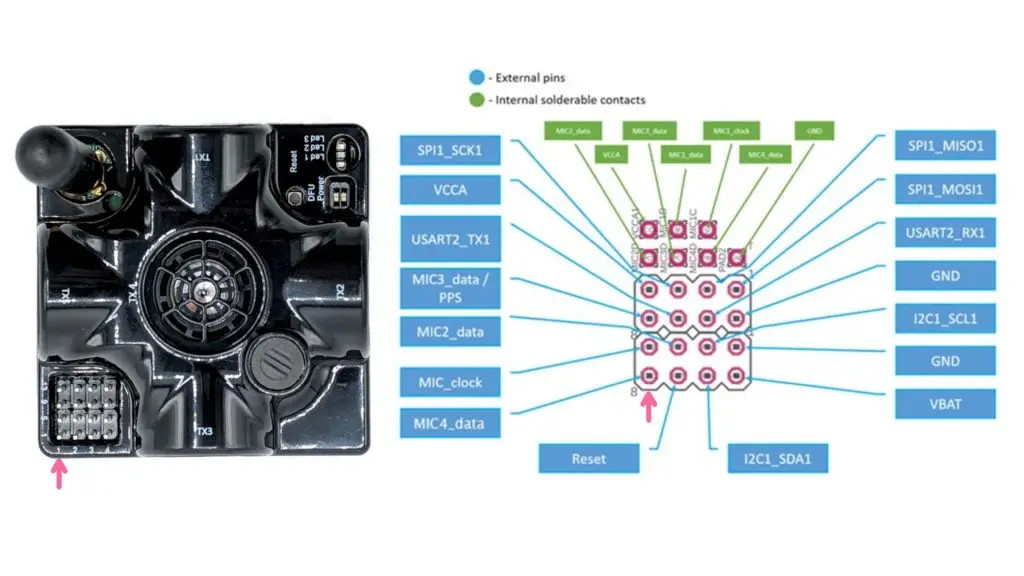
4x4 pins of Super-Beacon
The 4×4 pins of Super-Beacon provide great flexibility to connect to the Super-Beacon over multiple different interfaces physically:
The 4×4 pins of Super-Beacon provide great flexibility to connect to the Super-Beacon over multiple different interfaces physically:
- UART 3.3V – basic UART connectivity, for example, to your Pi or Arduino boards
- MicX_data – data from External Microphones or an Omni-Microphone. It is possible to connect up to three external microphones and one internal (RX1). Or it is possible to unsolder the internal microphone and replace it with an external one. Only one Omni-Microphone can be connected to the beacon because the Omni-Microphone already includes four basic microphones
- Mic_clock – clocks for External Microphones and an Omni-Microphone
- SPI pins – Super-Beacon supports SPI interfaces in hardware. However, nobody really asked for it; thus, the software support is currently not available
- I2C pins – used for compass/magnetometer simulation for PixHawk connectivity, for example. Can be used for receiving a location data stream as well
- VBAT – direct connectivity with the internal battery – to supply external loads, for example, your devices. It can be used to connect to a larger external LiPol battery with caution
- VCCA – output pin of clean 3.3V analog voltage to supply external loads, for example, external microphones and similar, up to 200 mA
- Reset – pin for external reset – in parallel with the internal Reset button
- GND – ground pins
Some of the pins can be repurposed based on your request (this will involve customized software development) to perform different actions. For example, this was the case for the optional SW feature MMSW0006: Dedicated pin for geofencing alarm.
The 4×4 pins are used for easy connection with Omni-Microphone, for example.
Industrial connectors for Industrial beacons and Super-Modem
All Industrial beacons and the Super-Modem are equipped with industrial connectors. The connectors protect up to IP67.
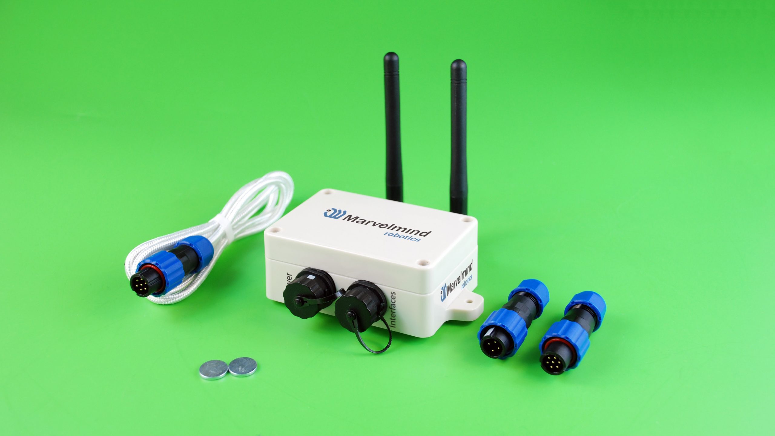
Industrial Super-Beacons, Industrial-RX, Industrial-RX with Omni, and Super-Modem have identical connectors:
- 4-pin connector for power, Reset, and DFU
- 7-pin for interfacing and power