Radio connectivity – basic hints
Intro
The article focuses on radio connectivity for Marvelmind Precise Indoor “GPS.” But most hints and advice are applicable and valid for the wide range of systems using radio connectivity: from remote-controlled toys to complex autonomous robotics systems for industrial applications.
Background
- Precise clock synchronization and data/telemetry transfer over the radio in license-free ISM/SRD bands between all network elements
- Multilateration based on precise distance measurements using the time of flight of ultrasound pulses
Radio connectivity between what exactly?
First of all, check the Architecture comparison document. Note, that the modem controls beacons over radio in a star architecture, i.e. beacons can hear each other, for example, hedgehogs can know other hedgehogs’ locations in this way, but currently all beacons talk to the modem – the main controller of the system – they don’t talk to other beacons over radio.
Thus, the answer is that the radio connectivity must be provided between the modem and the beacons it controls.
Today, Marvelmind Indoor “GPS” system typically uses only one modem, which typically supports up to 250 beacons (stationary and mobile combined). If there is more than one modem, it means that there are just two Marvelmind systems deployed.
For larger networks, it is possible to deploy a Multi-Modem Architecture – see a slide “Tunnel safety and performance” in the presentation dedicated to the Multi-Modem Architecture. In the Multi-Modem Architecture, each modem controls its map of stationary beacons. Mobile beacons (hedgehogs) freely roam between the maps using handovers. Modems, which are typically built on the Super-Modem’s hardware, are sending the location data from their respective maps to a Super-Super-Modem, and they are controlled by the Super-Super-Modem. The Super-Super-Modem and modems are connected using regular IP over 3G/4G/5G or WiFi, since the microsecond-level latency/jitter are not required for this connectivity unlike in the connectivity between the modem and the beacons it controls.
RSSI - what is it?
RSSI or Received Signal Strength Indicator is a level of radio signal received from a transmitter. What to remember in practice:
- There is RSSI from modem to beacon and from beacon to modem. If both devices are equal, which is usually the case, the RSSI levels in both directions must be the same, which means ±5dB or so. If it is more than that, for example ±10-15dB, it is a strong indicator that something may be wrong. For example, if the receiving part of a beacon is half-killed, which is possible, if it is killed by a static electricity discharge, for example, then the beacon to modem RSSI will be good, because the transmitting part of the beacon is OK and the receiving part of the modem is OK. But since the receiving part of the beacon is not good, the beacon’s receiver will be almost deaf, but not completely. And there might be a big difference in the RSSI readings
- RSSI is measured in dBm, which is dB (decibels to milliwatt (mW)). +20dB difference means 10 times stronger signal in voltage and 100 times stronger signal in power. -30dB difference means 31 times weaker signal in voltage and 1000 times weaker signal in power
- dBm is a measurement of power or RSSI, whereas dB is the measurement of difference. Difference of anything: power, voltage, brightness, etc. dBm is a difference as well, but to a fixed value, which is difference to mW
- The RSSI is often used as a term for the signal strength – not as just a term for an “indicator”. So, when we say: “check your RSSI”, we effectively mean: “check that your signal strength is not too strong or too weak”. Recommended RSSI is limited from the top with saturation of receiver and resulting signal distortion and from the bottom – by the noise of the receiver and resulting signal to noise ratio. Too low signal to noise ratio will result in bit losses and then packet losses and, as a result, the complete loss of work of the system
What is too strong and what is too weak?
- Too strong: the RSSI is more than -20dBm. Most likely, you have the modem and the beacon too close. We recommend to keep the modem 1-2 meters away from the beacon – it depends on the relative positions and the types of antennas
- Too weak: usually, below -90dBm, but it depends on the radio profile. Sensitivity of 38kbps radio profile is several times higher than that of the 500kbps radio profile
ISM vs. SRD bands and 433MHz vs. 915MHz bands
ISM radio and SRD radio bands are the terms used almost interchangeably. Both radio bands are dedicated for the license-free usage. License-free usage for the end-user – not for the manufacturer:
- ISM standards for: industrial, scientific and medical
- SRD stands for “short-range devices”
- Low-power (10-100mW or 10-20dBm) – to have an intentionally short range to allow many systems to co-exist in the same geographical area
- Co-existence with other systems in the same band/channel. Thus, interference is a not rare event, but is there by definition
- Frequency hopping
- Listen-before-talk
433MHz vs. 915MHz comparison
433MHz
Pros:
- Lower attenuation – the largest radio range
- Fewer external interferers (typical)
Cons:
- Larger antennas – more difficult to fit
- Nearly impossible to have embedded or ceramic antennas
- Narrow band – just 1.7MHz in 433MHz vs. 26MHz in 915MHz band
915MHz
Pros:
- Wide band – more channels and more capacity
- Possible to have embedded antennas. Not perfect or efficient, but better that nothing
Cons:
- Not as many as in 2.4GHz, but quite populated. Potentially more interference than in 433MHz
915MHz vs. 868MHz comparison
915MHz
- Used widely: USA, Japan, Korea and many other countries
- ISM band
868MHz
- Used mainly in the EU, China, Russia and a few other countries
- SRD band
- Narrow as compared with the 915MHz
Common for both – 915MHz and 868MHz:
- Typically, to cover both bands the same hardware (radio and antennas) is used, because the bands are relatively close to each other and matching circuitry and antennas are wideband enough to cover both bands at once. This facts increases the popularity for manufacturers, because only one type of hardware is required for both bands
- Radio range is nearly identical, because the frequencies are close
Why not 2.4GHz?
The 2.4GHz is very popular and has plenty of advantages:
- It can be used in nearly all countries, i.e. only one hardware can work in all those countries
- The band is wide: many channels => high capacity; high baudrate => high location update rate
- Small embedded or ceramic antennas work very well
But the main advantages of the 2.4GHz made it too popular for the manufacturers and lead to its main disadvantage:
- The band is overpopulated: too many WiFi devices, too many Bluetooth devices; too many telemetry, cameras, remote controls. As a result, in many cases, there is a way too high packet error rate due to the constant radio collisions and interference between different radio systems
- Overpopulation is OK for non-time critical transmissions: data, video
- It is more critical for the real realtime video, for example, FPV (First Person View) drones
- And it is absolutely critical for the realtime positioning systems like Marvelmind Indoor “GPS”. If the packet is lost now, usually, it is not interesting anymore later, because it is too late, because the data is not realtime anymore – there is a new packet co. Not always, but in many use cases. Therefore, only radio connectivity with real realtime connectivity and minimum lost packets are useful for realtime positioning systems, i.e. 2.4GHz can be used, but with limitations and trade-offs
Another limitation of the 2.4GHz band is higher loss of radio

Frequency of 915MHz is about 2 times higher than the 433MHz band:
- Thus, the path loss is about 4 times higher over the same, distance, i.e. 12dB
For 2.4GHz, the frequency is about 2.5 higher than the 915MHz band and 5.5 higher than for the 433MHz band. As a result:
- The losses in 2.4GHz are respectively 6.25 times or 16dB higher vs. 915MHz band
- And 30 times or 30dB vs. 433MHz band
Radio profiles - how to choose
We created several predefined radio profiles. It is done in order to simplify the options. In practice, there are so many radio settings, that it is impossible to choose properly without a special tool. But, if for some reason you need something special – apart from the predefined profiles – let us know via info@marvelmind.com and we will create a special radio profile for you.
400/500kbps
- The highest bandwidth and baudrate
- The highest potential location update rate, if limited by the radio. Though, typically, limited by the ultrasound
- The least sensitivity and the shortest radio range
- The least protection against external interference
100/153/200kbps
- Balanced and average everything: update rate, sensitivity, resistance to external interference
- Typical default settings
38kbps
- The highest sensitivity and the longest radio range
- The highest resistance against the external interference
- The lowest update rate, if limited by radio
- It has been a default setting in some SW version in order to provide the best compatibility between different hardware variants or between different types of beacons, because different radio chips have different radio settings and it is not easy to find a common one suitable for all of them
Key radio elements and factors
Antennas
Standard antennas are supplied with Super-Beacons, for example. They are short – 50mm. Size affects the performance. In a typical open-space environment they provide up to ~100m radio coverage radius to the similar standard antennas on the Modem v5.1. Standard antennas are omni-directional shortened quarter-wave antennas.
Full-size antennas are larger – 80-160mm – depending on the band. They are more efficient and provide 3-6dB gain – i.e. 1.5-2 time larger range in radio. If used on both ends – beacon’s side and the modem’s side – they allow up to ~400m typical radio range in open space. Full-size antenna are omni-directional quarter-wave antennas.
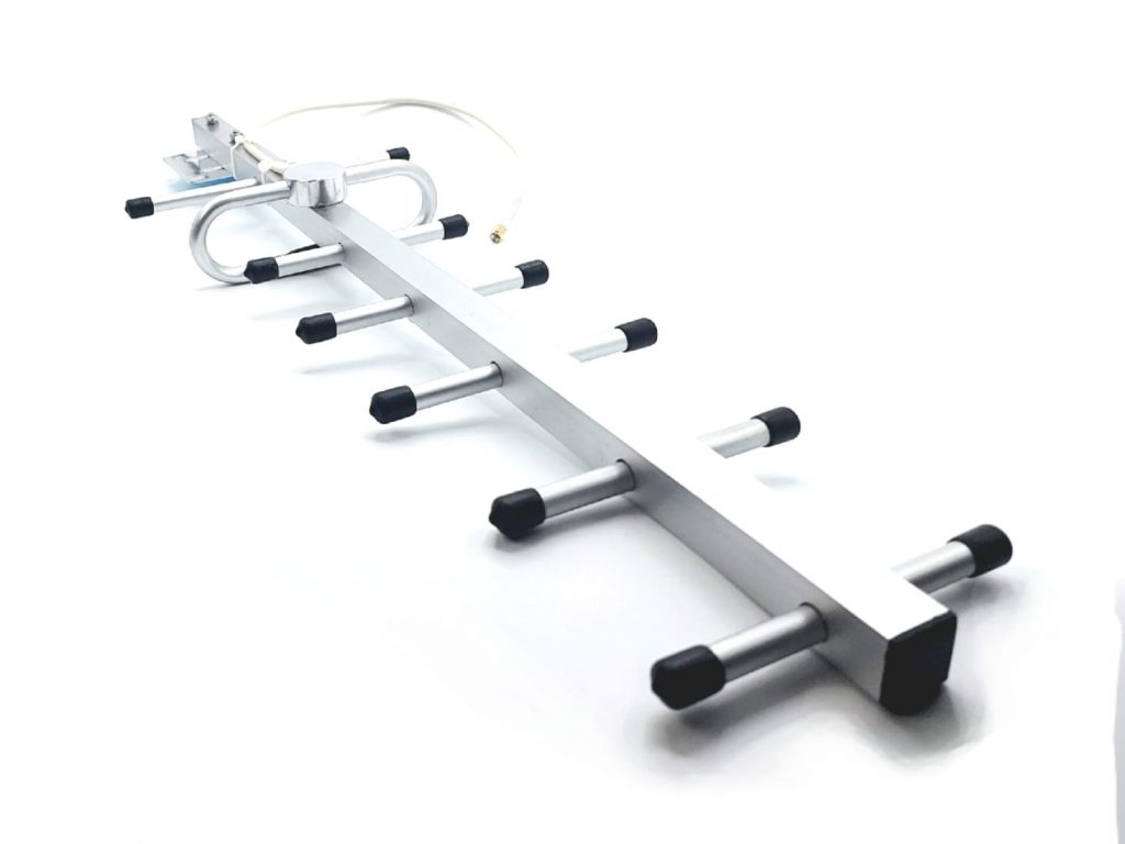
Directional antennas provide even larger range or stronger radio signals and they have a typical gain of 6-16dB, i.e. can provide 2-6 larger distances. Since they are directional, special considerations must be met to provide the proper coverage. For example, it is worth placing the directional antenna in one size of the elongated warehouse and coverштп the whole warehouse from that side. As an alternative – to place a larger gain full-size omni antenna or two directional antennas back to back facing outwards in the middle of the warehouse. Combining two antennas back to back requires a splitter and additional cables. All of these devices add losses to the radio signal and increase the costs and the complexity. Thus, proper radio planning becomes challenging.
Embedded antennas are used in Mini-RX and in Mini-TX. They have a poorer radio performance as compared to the regular antennas. However, they are very small and placed directly on the board. Their size is the only advantage. The range of ~50-100m is enough for many applications and many use cases. When the radio range of the embedded antenna is not enough, an external antenna is connected to the Mini-RX, for example, in the Badge configuration.
Typically, the easiest and the least expensive way to provide the radio coverage is to improve the antennas:
- First – on the modem’s side, because the modem’s connectivity affects all beacons
- When improvements on modem’s antenna becomes insufficient – it is time to improve antennas on the farthest beacons
Antenna polarization
Antennas have polarization. Typically, either horizontal or vertical. Circular polarization is also possible, but not typically used in Marvelmind systems.
Polarization is a simple thing for practical implementation: in order to provide optimal radio connectivity, transmitting and receiving antennas must have the same polarization. As simple as that.
Vertically polarized transmitting antennas work the best with vertically polarized receiving antennas and vice versa. The same for horizontal polarization.
Vertically placed antennas, for example, Standard antennas or Full-size antennas, will have the vertical polarization. Placed horizontally, they will have horizontal polarization.
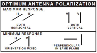
We recommend to use the vertical polarization. It is simply more implementable and practical in real-life cases:
- All beacons have vertically placed antennas
- All modems have vertically placed antennas
- Directional antennas have a polarization sign. Rotate and install the antennas accordingly
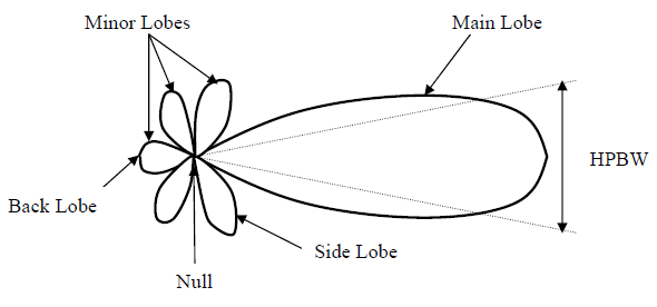
Antenna radiation pattern
Standard and Full-size antennas are formally speaking omni-directional. But, in reality they are omni-directional in the horizontal plane, if they are placed vertically. In the vertical plane they have a theoretical gain dip to zero. In practice, the gain in the direction where antenna points is not zero, but can be significantly smaller than to the direction perpendicular to the antenna.
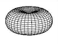
It is very difficult to talk about the radiation pattern of the embedded antennas. They may be considered to be omni-directional, but with lower gain and efficiency.
Directional antennas clearly have the direction(s) with higher gain.
Interference
There could be multiple sources of interference:
- Since Marvelmind systems work in ISM/SRD radio bands, other systems can easily work on the same radio channels, because ISM and SRD bands are not reserved to a particular user and different systems must co-exist. Thus, the interference is not improbable at all
- In practice, however, interference is rather rare, unless you have other your own radio systems next to Marvelmind system, for example, telemetry for PixHawk using the same 915MHz band or an adjacent 868MHz band. It doesn’t necessarily have to be the same channel. If the antennas are close enough and the signal is strong enough, the radio connectivity may be severely affected or blocked completely
- Marvelmind is using under-1Ghz license-free bands, because higher-frequency bands such as 2.4GHz and 5.6GHz are very much polluted by multiple sources: WiFi, Bluetooth
Typical potential suspects:
- Other Marvelmind systems, for example, another Marvelmind modem on the same channel. There must be only one active/powered Marvelmind modem per radio channel
- Other radio systems next to Marvelmind beacons or modem, for example, telemetry for PixHawk or some radio control units or alarms
- Walky-talky and other radios. They may be in the same band or channel, then even a small power could affect. Or they may be on completely different channels/bands, but so powerful that they simply saturate Marvelmind radio. Marvelmind beacons and modem emit under +10dBm or 10mW or power, that can be 1000 times lower than some powerful handheld radio
- Industrial interference: powerful welding, powerful sparks – not highly probable, but still
- Induction ovens and similar. They are usually using 2.4GHz band, but being powerful and close enough, potentially, may affect, albeit not very likely
Potential mistakes and problems and how to avoid them
Broken antennas
Antennas are a mechanical element and they can be pretty easily broken, because antennas stick out from the beacons/modems. Make sure they are not mechanically hit or bent where they are not bendable.
Not mating connectors
We are using reverse SMA connectors in the majority of our equipment. They are considered non-standard connectors, because they are reversed. It is done in order to pass, for example, the FCC (USA) radio certification that requires that antennas are not easily interchangeable, i.e the antennas having non-standard mating connectors as well.
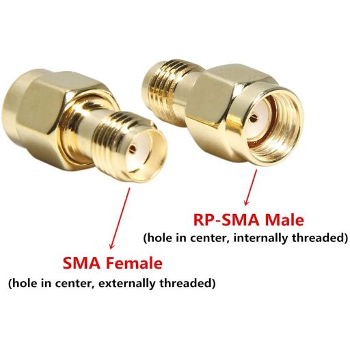
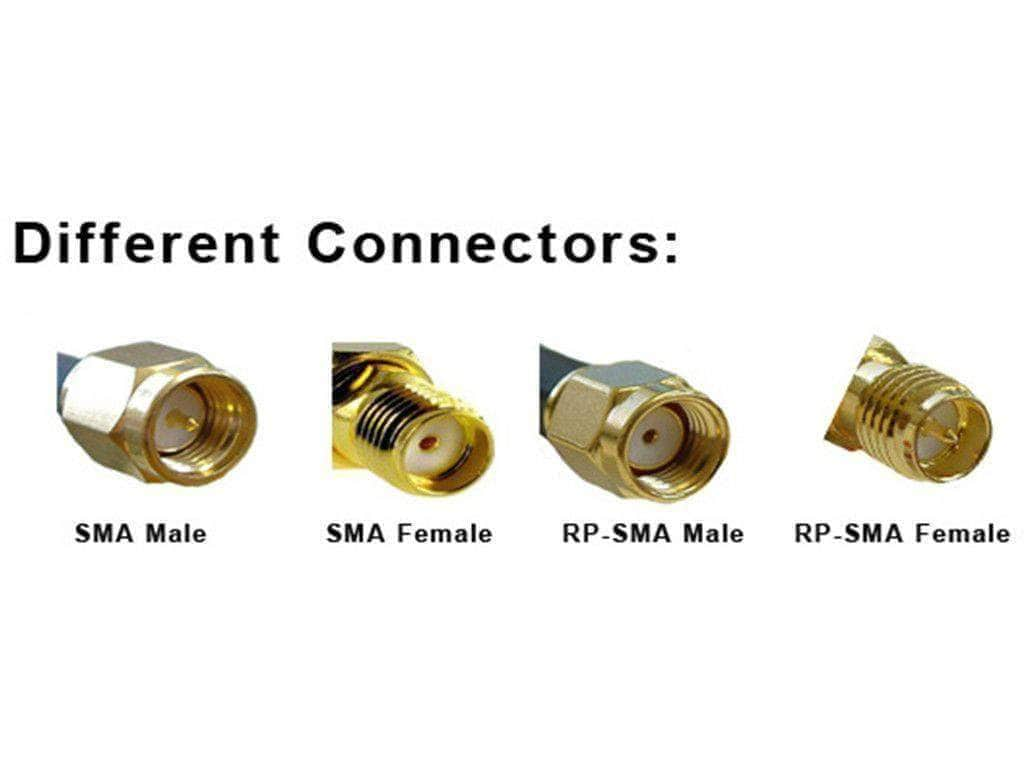
It is very easy to wrongly connect SMA female and reverse SMA male. The connectors will be screwed together well, but there will be no electrical contact. For the external user everything will look like poor radio connectivity.
Antennas are too close to metal or other conducting materials
Antennas must be 1-2 wavelengths from metal parallel to antennas. For the Marvelmind system, it is 50-100cm.
At the same time, antennas/beacons can be placed on the metal easily, if the antennas are perpendicular to the metal. It is possible, because there will be a mirrored virtual antenna in the metal. If parallel and close, it would kill the radio signal. If perpendicular, it will affect mildly or may even improve in some cases.
Proximity to other materials than metal can be affecting as well. For example, concrete, wood, etc. The impact depends on the conductivity of the materials, its permittivity and permeability.
In case of doubts, the recommendation is very simple: keep at least 50-100cm from metal, wires, walls. If not possible, make antennas perpendicular to those wires, metal, walls. Remember to keep the antennas vertical and parallel to antennas of other radio devices in the Marvelmind network.
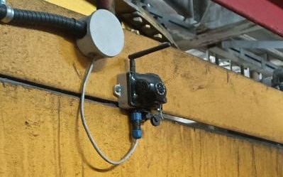
Example of a very bad antenna placement: antenna is just a couple cm from a metal. The radio performance of the antenna would be completely ruined the radio range suffers most likely significantly
A better placement, but not perfect: antenna is bent and from vertical polarization it becomes horizontal. But it is perpendicular to the metal now and its performance won’t be killed. The horizontal polarization is potentially reducing the performance, but it is a forced and reasonable compromise with the results most likely much better than that in the example above. The antenna position is also not perfect because it is too close to the grey electric splitter. The splitter must be 50-100cm away or behind the antenna to reduce the impact on the antenna
Antenna is placed OK: it is vertical; relatively far from the metal or perpendicular to metal. What shall be improved? – to move right more – farther from the parallel metal part on the left
Radio cannot go through metal walls
Obviously, radio cannot go through metal walls. Thus, if you need to track something inside a huge oil or water tank or even inside a van, you must place the beacons and the modem inside the tank as well. See the example:
In some cases, the modem may still be outside, but not because the radio goes through the walls, because it can leak inside via holes or slots. Yes, with losses, but the signal (RSSI) can be still sufficiently strong, and the system may operate without problems. So, you can always test and check.
Polarization and radiation diagram
Already discussed in detail above. Keep antennas with the same polarization – the easiest: vertical and parallel. Otherwise, it is possible to significantly reduce the radio range.
Multi-path propagation
Since Marvelmind Indoor “GPS” systems are typically used indoors, there is always a multi-path radio propagation. The result is that the radio signals may randomly sum up from different directions and be 2-3 times stronger in a particular point; but they can subtract and become 10-100 times lower.
Moreover, the multi-path propagation is not a static process. Something huge and made of metal may be moving dozens of meters away, for example, a forklift or a crane, but the RSSI will be impacted at the antenna point, which is next to you.
Often, if you have difficulties with RSSI, it is worth trying to move the antenna/beacon/modem 10-30cm around the point of the current location. You may see a significant change in the RSSI. But remember, that everything affects the performance. You can’t just tune it and be sure it will stay, since your own body/arms affect the performance. Thus, often it is a try-and-error work until the best radio performance (strongest RSSI and no packet loss) is achieved.